AG-tronik M1 AND REGULATOR PR-9
INSTRUCTIONS FOR USE – rev. 2017-04
69
16.
WIRING DIAGRAM
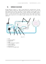
Wiring diagram on figure is a classic wiring diagram for spraying devices. Pressure
regulator consists of central valve, distribution valves, flow meter, filter... Flow travels from
tank through suction collector and pump to pressure regulator. Central MAIN valve is
basically an option valve, which directs flow to nozzles and other devices (filling container,
mixing...) or back in the tank. Electric motor distribution valves ensure supply of chemicals to
nozzles, other manual valves are intended for supply of mixing nozzle, tank cleaners, filling
container...
2
9
1
5
4
3
6
7
8
Figure 122
1.
tank
2.
pressure regulator
3.
sucking filter
4.
pump
5.
blower with sprayer segments
6.
intake manifold
7.
valve for discharge
8.
mixing nozzles
9.
nozzles for cleaning the tank


