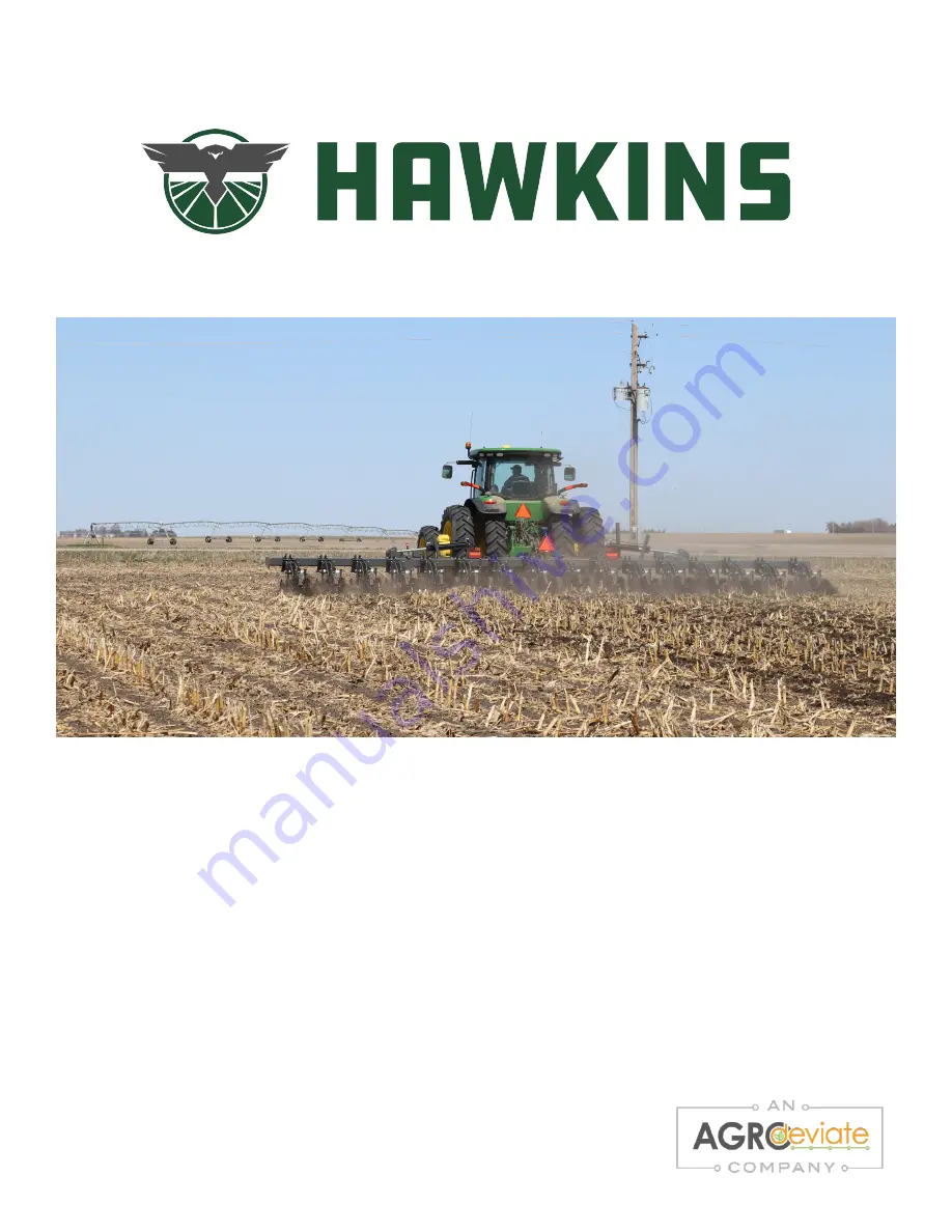
AGROdeviate Hawkins StripCat Скачать руководство пользователя страница 1

308.708.8185 | [email protected]| Rev. 01/21 | Part Number 123013

STRIPCAT™

OWNER’s Manual

R

evised 01.21

Содержание Hawkins StripCat

Страница 1: ...308 708 8185 Hawkins HawkinsAg com Rev 01 21 Part Number 123013 STRIPCAT OWNER s Manual Revised 01 21 ...

Страница 2: ... The serial number provides important information about your StripCat and may be required to obtain the correct replacement part Always provide the model number and serial number to your Hawkins Ag dealer when ordering parts or anytime correspondence is made with Hawkins Ag SERIAL NUMBER Record the model number and serial number of your StripCat along with date purchased This manual is applicable ...

Страница 3: ...if damaged All reflective decals and SMV sign correctly located and visible when the machine is in trasport position Safety warning lights correctly installed and working properly Paint all parts scratched during shipment or assembly All safety lockup devices on the StripCat are correctly located Use the following checklist after your StripCat is completely assembled Check off each item as it is f...

Страница 4: ...autions Along with retail customer end user check reflective decals and SMV sign are clearly visible with StripCat in transport position and attached to tractor Check safety warning lights are in working condition Tell retail customer end user to check federal state provincial and local regulations before towing or transporting on a road or highway GiveOwner sManualandallInstructionSheetstoretailc...

Страница 5: ... 25 GAUGE WHEEL ADJUSTMENT 26 DOWN PRESSURE SPRINGS 27 ROW UNIT DEPTH ADJUSTMENT 28 KNIFE PLATE 30 RESIDUE MANAGER 31 ROW CONFIGURATIONS 32 INDEPENDENT BERM BUILDERS 33 REAR FINISHING TOOLS 39 HYDRAULIC TRIPPING UNIT 40 BAR STANDS 43 OPERATING TIPS OPERATING SPEED 44 PARKING STORAGE 46 DO S AND DON TS 48 TROUBLESHOOTING TROUBLESHOOTING 49 MAINTENANCE LUBE GENERAL MAINTENANCE 52 MAINTENANCE SCHEDUL...

Страница 6: ......

Страница 7: ...ns Ag reserves the right to change specifications or design without notice and without incurring obligation to install the same on machines previously manufactured Right hand and left hand as used in this manual are determined by facing the direction the machine will travel while in use HOW TO USE THIS MANUAL Replacement manuals are available Call the Hawkins Ag Main Office at 308 708 8185 or down...

Страница 8: ...ipment are warranted through the respective tire manufacturer and their network of dealers All returns must be pre approved by AGROdeviate and authorization issued before return All returns must include a copy of the original invoice in order to be processed Any returns without a copy of the original invoice will not be eligible to receive credit If determined that the product is defective in mate...

Страница 9: ... the manual is damaged please contact AGROdeviate 124 W 25th St Ste C5 Kearney NE 308 708 8185 or visit our website www hawkinsag com DANGER WARNING CAUTION DANGER Indicates an imminently hazardous situation that if not avoided will result in death or serious injury This signal word is to be limited to the most extreme situations typically for machine components which for functional purposes canno...

Страница 10: ...or to use Replace any CAUTION WARNING DANGER or instruction safety decal that is not readable or is missing Location of such decals is indicated in this booklet Do not attempt to operate this equipment under the influence of drugs or alcohol Review the safety instructions with all users annually This equipment is dangerous to children and persons unfamiliar with its operation The operator should b...

Страница 11: ......

Страница 12: ...own in the illustrations below Good safety requires that you familiarize yourself with the various Safety Signs the type of warning and the area or particular function related to that area that require your SAFETY AWARENESS 461230 461259 461220 461250 461255 461248 461225 461213 NOTE LH RH Safety Signs and locations are similar SAFETY ...

Страница 13: ...butarenotlimitedto hingemechanismmovement pinmovement row unit movement and shifting accessory movement and shifting etc CRUSH HAZARD WARNING Keep clear of moving and shifting equipment Equipment movement area will result in death or serious injury Hazards may include but are not limited to connection and disconnection of equipment unexpected equipment shifting etc 461213 461220 SAFETY ...

Страница 14: ...n death or serious injury Hazardsmayinclude butarenotlimitedto foldingwingmovement raised equipment movement and shifting etc NO RIDERS WARNING Never allow riders on equipment can result in death or serious injury Hazards may include but are not limited to falling from equipment falling into equipment injury while on equipment etc 461225 461230 SAFETY ...

Страница 15: ...s may include but are not limited to damaged tire and or rim over pressurized tire excessive tire wear tire tears or punctures ect HIGH PRESSURE FLUID DANGER Use safe practices Fluid injection can occur will result in death or serious injury Hazards may include but are not limited to injury beyond the entry point over pressurized components damaged components components with excessive wear swollen...

Страница 16: ... Hazards may include but are not limited to high clearance equipment low clearance power lines lack of awareness of surroundings etc READ UNDERSTAND MANUAL CAUTION Do not operate without a complete understanding of the owner s manual Do not operate with unsafe practices may result in death or injury Hazards may include but are not limited to compromising the safety of yourself and or others lack o...

Страница 17: ...acking paper Remove the smallest portion of the split backing paper Align the decal over the specified area and carefully press the small portion with the exposed stick backing in place Slowly peel back the remaining paper and carefully smooth the remaining portion of the decal in place Small air pockets can be pierced with a pin and smoothed out using the piece of decal backing paper REMEBER If S...

Страница 18: ......

Страница 19: ...if damaged See Safety Sign Locations starting on page 5 On initial delivery use with a new tractor and seasonally check and as necessary complete these items before continuing to the routine set up items Bleedhydraulicfoldsystem page54 Check ChangeHitchConfiguration HitchingTractortoImplement HydraulicHoseHook up LightKitGuideandRelocation ElectricalHook up LevelingtheImplement PRE TILLAGE SET UP ...

Страница 20: ...e routine set up items Choose a hitch option that is compatible with your tractor 3 point The StripCat has two hitch configurations Changing between hitch categories requires removing pins at the implement hitch TO OPERATE AS CATEGORY 3 1 Remove and store the Category 4 pins 2 Once removed the remaining pins are set to run the implement with a Category 3 hitch Category 3 Category 4 SEE NEXT PAGE F...

Страница 21: ...08 8185 Hawkins HawkinsAg com Rev 01 21 TO OPERATE AS CATEGORY 4 1 Remove and store the Category 3 pins PREPARATION SET UP 2 Once removed the remaining pins are set to run the implement with a Category 4 hitch ...

Страница 22: ...WARNING Keep clear of moving and shifting equipment Equipment movement area will result in death or serious injury Hazards may include but are not limited to connection and disconnection of equipment unexpected equipment shifting etc 461220 1 Connect the tractor 3 point lift arms to the lower hitch pins If using a quick hitch ensure that the pins lock securely 2 Connect the top link to the upper h...

Страница 23: ...ect 461250 1 Connect fold hoses for left wing into remote valve of choice 2 Connect fold hoses for right wing into remote valve of choice 3 If your machine is equipped with hydraulic tripping function connect hoses from tripping manifold to remote valve of choice 4 Check and make sure all hoses are tied up and secure before use The StripCat is equipped with independently controlled fold cylinders ...

Страница 24: ... or lights may need relocated before use Typically the SMV sign is the only component that needs relocated please check all components Check that all forward facing reflectors and lights are visible from the front and all rear facing reflectors and lights are visible from the rear Please refer to the depiction below for component locations LIGHT KIT GUIDE AND RELOCATION PREPARATION SET UP ...

Страница 25: ...andard 7 pin connector To connect simply lift receptacle cover align plug and insert To disconnect lift receptacle cover and remove plug Once connected check to make sure all lights are working properly If lights are not working properly contact your dealer to fix before transporting on public roadways 7 pin Connector ...

Страница 26: ...veling bolts 4 If wing is too high tighten bolts in 1 4 1 2 turn increments unfolding machine to re check level If wing is too low loosen bolts in 1 4 1 2 turn increments unfolding machine to re check level 5 Repeat process until wing is level Front to BackLeveling See Leveling the Machine on page 25 This adjustment needs to be completed in field conditions Figure 1 Figure 2 Figure 3 Ring Cotter P...

Страница 27: ......

Страница 28: ... learning process or take the unit for granted Ease into it and become familiar with your new equipment Practice operation of your equipment and its attachments Completely familiarize yourself and other operators with its operation before using Your best assurance against accidents is a careful and responsible operator If there is any portion of this manual or function you do not understand contac...

Страница 29: ...ng steps before transporting the StripCat to the field Carefullyread ImportantSafetyInformation onpage3 Lubricateimplementasindicatedunder Maintenance Lube onpage53 Checkalltiresforproperinflation Checkallbolts pins andfasteners Torqueasshownin BoltTorqueChart onpage55 Checkimplementforwornordamagedparts Repairorreplacepartsbeforegoingtothefield Checkhydraulichoses fittings andcylindersforleaks Re...

Страница 30: ...on locking position before folding the wing s To move wing lock pin position pull ring cotter pin Then pull the pin out of the toolbar and reinsert it into the desired position Insert the ring cotter pin WING LOCK PINS OPERATION Ring Cotter Pin Wing Lock Pin Non Locking Position Storage Lock Position Leveling Bolts ...

Страница 31: ...ious injury or death and certain severe equipment damage When unhitched the implement is supported at the rear only by row unit tools and spring tension Slopes soft soils and soils later softened by rain are particularly dangerous ELECTRICAL SHOCK ELECTROCUTION HIGH CLEARANCE DANGER Keep clear of overhead power lines maintain 20 foot minimum distance Electrical shock and or electrocution can occur...

Страница 32: ...ld topple backward or forward immediately or at a later time causing serious injury or death and certain severe equipment damage When unhitched the implement is supported at the rear only by row unit tools and spring tension Slopes soft soils and soils later softened by rain are particularly dangerous ELECTRICAL SHOCK ELECTROCUTION HIGH CLEARANCE DANGER Keep clear of overhead power lines maintain ...

Страница 33: ...to highclearanceequipment low clearance power lines lack of awareness of surroundings etc BRAKING AND LOSS OF CONTROL HAZARD Do not exceed 20 mph 32km h when driving straight Do not exceed 13 mph 21 km h in turns The weight of the implement can cause under steer and the height of the implement is a tipping hazard CAUTION DANGER TRANSPORT CHECKLIST Before transporting the implement check the follow...

Страница 34: ...ement section on page 18 In order to set front to back level of machine pull into field then lower implement in ground Go a short distance while leaving the machine in the ground Stop put tractor into park Then adjust toolbar height so that bottom of the toolbar measures between 23 24 to the ground Once toolbar is set to proper operating height adjust third link on tractor until toolbar is level L...

Страница 35: ...ut The second method of adjustment is to change the lower position of the ratcheting turn buckle The ratcheting turn buckle s standard location is in the center of the 3 holes on the lower arm and is the recommended setting for the StripCat The gauge wheels are designed to help the tractor carry the machine through the field and hold proper depth NOTE Gauge Wheels are optional accessories and do N...

Страница 36: ...w unit can be adjusted by changing which pin hole the spring retainer is set at FRONT HOLE Lightest down pressure for light or sandy soils MIDDLE HOLE Medium down pressure for most soil types REAR HOLE Maximum down pressure for high clay soils compacted soils and heavy residue REAR HOLE FRONT HOLE MIDDLE HOLE ...

Страница 37: ...sive knife blowout and or machine wear We make no recommendations for products placement or timing of fertilizer applications Refer to your agronomist for products placement depth and timing for fertilizer application that fit your operation Recommended Toolbar Height 23 24 Depth Gauge Wheels Hole Setting 20 Coulter Cutting Depth Knife Plate Setting Knife Depth Top 7 5 Top Bottom 8 9 5 2nd 6 Top B...

Страница 38: ... depth by changing the hole position of the depth gauge wheels The factory setting is the second hole from the top To adjust depth remove the 5 8 bolts from each side using a pair of 15 16 wrenches Depth adjustment must be done on each side of the row unit Factory Setting OPERATION Increase Depth Decrease Depth ...

Страница 39: ...e You may also have to loosen the bolts that hold the row cleaner tube to allow for free movement of the knife plate within the row unit side plates to complete this process The factory setting is the lower set of holes Knife Plate Bolts Row Cleaner Tube Bolts Mini mole with dual 3 8 tubes for Liquid and NH3 333890 Mini mole with 1 1 2 Dry Tube and 3 8 Liquid Tube 333891 Mini mole with 1 1 2 Dry T...

Страница 40: ...moved To adjust the residue manager remove the 1 2 retention pin with one hand while supporting the assembly with your other hand raise or lower the assembly to the desired location and reinsert the pin in the next available hole There are two 2 holes in the residue manager stem allowing for half step precise adjustments of the residue managers Residue Manager OPERATION CAUTION Residue Manager bla...

Страница 41: ...from the factory in left hand and right hand configurations based on which side of the residue managers and Independent Berm Builders lead and trail Row units are alternated left and right across the machine to allow residue to flow between the units Right Hand Row Unit OPERATION Left Hand Row Unit ...

Страница 42: ...NDENT BERM BUILDERS The Independent Berm Builders on StripCat have numerous adjustable features which allow you to customize your strips You can adjust down pressure blade fore aft blade toe angle blade depth and distance between the blades Independent Berm Builders ...

Страница 43: ...e is needed To increase down pressure on the berm building discs tighten the 3 4 nylon lock nut on the IBB arm compression spring To decrease pressure loosen nut This adjustment can be checked by measuring the distance from the spring mount place to the top of the spring cap The factory setting is approximately 7 25 and can be adjusted from 6 to 7 5 Compression Spring Nut Max Distance 7 5 Min Dist...

Страница 44: ...of disc moved inward more soil will be moved into the strip increasing the size of the berm created by the machine To adjust the pitch of the IBBs loosen the carriage bolt on the adjustment plate with a 3 4 wrench you may also have to loosen the pivot bolt with a pair of 15 16 wrenches then adjust the angle of the discs to your preference and retighten bolts In most cases the left and right discs ...

Страница 45: ...sc hub is bolted into This adjustment allows for 1 1 4 of difference in blade depth To change the depth of the blades use a 1 1 8 socket to remove the 3 4 nut from the carriage bolt move the bolt to the other hole making sure to get the same number of washers between the hub and stem plate as before removal and retighten in the new position Shallower Position Deeper Position ...

Страница 46: ... poly spacer blocks can be removed or added on each side of the row unit Using a pair of 15 16 wrenches remove the two 5 8 bolts that hold the rear IBB arms in place and either remove or add the desired number of spacer blocks from each side Note Put unused spacer blocks on outside of arm to continue to use same length bolts Remove bolts Poly Spacer Blocks Remove bolts Recommended Number of Poly S...

Страница 47: ... the Berm Building Discs remove the two 5 8 bolts that attach the rear IBB arms to the front IBB arm using a pair of 15 16 wrenches Reinstall in the desired position and tighten bolts Adjustment holes Rear IBB Arm Front IBB Arm Factory Setting Left Hand Row Unit Left Arm short in forward holes Right arm long in rearward holes Factory Setting Right Hand Row Unit Right arm short in forward holes Lef...

Страница 48: ... be added removed by removing a 1 2 retaining pin Each accessory can be adjusted for height by placing the pin in different holes on the stem of the accessory To increase down pressure on the berm building discs tighten the 3 4 nylon lock nut on the down pressure spring To decrease pressure loosen nut Down pressure Spring 1 2 Retaining Pin Max Distance 7 25 Min Distance 5 5 Factory Setting 7 25 To...

Страница 49: ...w from the tractor to allow the knife plate to trip when encountering a hard object in the soil and reset itself automatically The resistance to tripping is controlled by the hydraulic system pressure and can be set between 500 and 2500 psi see page 42 for more details Knife Plate Tripping Cylinder Pressure Relief Adjustment Screw Tripping Hydraulic Block 46 ...

Страница 50: ...s are clear from the machine Cycle the system through the travel range of the cylinders and check that all rows function as expected Always place the system in float when performing work on the row units Pressurize the system and check that the gauge indicates the desired pressure If not adjust pressure screw Once you have performed a check and set the system pressure to a good starting point the ...

Страница 51: ...o the lowest pressure that keeps the knives in the ground but allows the units to trip when encountering an obstruction Lower pressures will prolong the life of the system and reduce knife breakage When setting your hydraulic tripping system start between 500 and 1000 psi and work up to find the best pressure for your conditions Refer to the chart below for recommended pressure adjustment incremen...

Страница 52: ...allows your machine to sit level when parked on the bar stands in the front with the knives supporting the rear of the machine On soft ground use wood blocks or steel plates to keep the bar stands and knives from settling into the ground and prevent the machine from becoming unstable or causing difficulties the next time you want to hook up to the machine Prior to unhooking the machine check that ...

Страница 53: ...on ridges it is recommended to use a root ball puller stalk chopper or rolling stalk chopper prior to strip tilling Some experimentation may be necessary to produce the best strips for your conditions KNIFE DEPTH A steel rod or wooden dowel can be inserted into the middle of the strip to check the depth of action of the knife Adjust the knives to suit your conditions fertilizer placement needs and...

Страница 54: ... the machine Slower speeds may result in inconsis tent strips Ideal operating speed 5 6 5 mph Minimum operating speed 4 mph Maximum operating speed 8 mph In most conditions speeding up will result in more soil disturbance knife blowout and wear on the machine In most conditions slowing down may result in inconsistent strips See troubleshooting section for more information on performance issues rel...

Страница 55: ...ink PARKING DANGER TIP OVER CRUSHING HAZARD AND EQUIPMENT DAMAGE RISK Never unhitch park or store a partially folded implement A partially folded implement could topple backward or forward immediately or at a later time causing serious injury or death and certain severe equipment damage When unhitched the implement is supported at the rear only by row unit tools and spring tension Slopes soft soil...

Страница 56: ... job at hand Use extreme caution when making adjustments Follow the torque chart in this manual when tightening bolts Replace all shields and guards after servicing and before moving After servicing be sure all tools parts and service equipment are removed Never replace hex bolts with less than Grade 5 bolts unless otherwise specified Refer to Bolt Torque Chart for head identification marking Wher...

Страница 57: ...r optimum performance DO lift implements completely out of the soil before turning the unit DO use caution when moving large equipment Using a spotter is recommended when working around obstacles on the ground and or overhead DON T fold the toolbar with locking pins in the locked position DON T over pressurize the hydraulic system StripCat hydraulics are designed for 3 000 PSI MAX working pressure...

Страница 58: ......

Страница 59: ... plug with residue between front coulter and row coulter Toolbar height levelness Adjust toolbar height level Wet damp conditions preventing good residue flow Wait for ground to dry Decrease ground speed to improve residue flow Adjust row cleaners up slightly to decrease residue load Bearing going out Check replace bearings Row units plug with residue between row cleaner and knife Toolbar height l...

Страница 60: ...ue flow Residue plugs between row units Not enough space for residue between knife and discs Adjust distance between discs and knife by adjusting berm building disc width with poly spacer blocks see page 37 Adjust distance between discs and knife by adjusting berm building discs fore aft on arms see page 38 Heavy residue conditions Adjust ground speed to improve residue flow Wet damp conditions pr...

Страница 61: ...s as small changes to pressure can have a large effect on tripping force NOTE Do not make changes to hydraulic flow from tractor Knives are shearing bolts system is not tripping Pressure relief valve set too high Decrease system pressure Pressure adjust ments should be made in 25 psi increments as small changes to pressure can have a large effect on tripping force NOTE Do no make changes to hyraul...

Страница 62: ......

Страница 63: ...ve wear swelling or damage Always replace bolts with the same grade refer to BoltTorque Chart for grade identification Tighten bolts according to Bolt Torque Chart Always replace parts with Hawkins parts only We recommend greasing each grease zerk on the toolbar hinge weekly Grease all attachment grease zerks weekly or according to specified lubrication schedule Before long term storage 3 months o...

Страница 64: ...sing hardware WEEKLY MAINTENANCE 1 Grease the toolbar hinges three 3 grease zerks on each hinge 2 Grease gauge wheel bearings YEARLY MAINTENANCE 1 Clean machine off 2 Grease all grease zerks 3 Replace all parts as necessary 4 Check Bolt Torque on Hubs Toolbar Hinge Gauge Wheel MAINTENANCE LUBE Grease Zerks ...

Страница 65: ...nders so they will not contact anything when extended 3 Loosen rod end hose fittings 1 at a ORB connection 4 Slowly supply oil to rod end of fold cylinders until oil appears at loosened hose fitting Tighten fitting and completely retract fold cylinders 5 With cylinders completely retracted loosen base end hose fittings 2 at ORB connection 6 Slowly supply oil to base end of fold cylinders until oil...

Страница 66: ...guide Replace hardware with the same grade bolt Torque Specifications Bolt Diameter Bolt Torque SAE Grade 2 SAE Grade 5 SAE Grade 8 INCH lbft Nm lbft Nm lbft Nm 1 4 6 8 9 12 12 17 5 16 10 13 19 25 27 36 3 8 20 27 33 45 45 63 7 16 30 41 53 72 75 100 1 2 45 61 80 110 115 155 9 16 70 95 115 155 165 220 5 8 95 128 160 215 220 305 3 4 165 225 290 390 400 540 7 8 170 230 420 570 650 880 1 226 345 630 85...

Страница 67: ...picted This chart is printed at 1 to 1 for ease of identification NPTF National Pipe Taper Fuel uses tapered threads to create a seal ORB O Ring Boss uses an O ring to seal after threads JIC Joint Industry Council 37 degree flare sealing surface before threads ORFS O Ring Face Seal uses an O ring to seal before threads 4 NPTF 6 NPTF 8 NPTF 12 NPTF 4 ORB 6 ORB 8 ORB 12 ORB 10 ORB 4 JIC 6 JIC 8 JIC ...

Страница 68: ...fluid used in the system Then tightening to a specified torque Do not force fittings together Ensure male and female are of the same type and size align sealing surfaces and threads properly Do not apply force to a connection or use the connection as support Doing so may damage components and or cause the connection to leak Torque lbft Nm Dash Size NPTF ORB JIC ORFS 4 12 16 16 22 10 15 14 20 11 13...

Страница 69: ......

Страница 70: ...kage Item Number Part Description Quantity 1 333046 LH MOUNT 1 2 333047 RH MOUNT 1 3 333012 TOP PARALLEL ARM ASSEMBLY 1 4 333011 BOTTOM PARALLEL ARM ASSEMBLY 1 5 333014 PARALLEL LINK SPRING RETAINER 1 6 333150 PARALLEL LINK SPRING 4 7 333020 BENT PIN 1 SEE NEXT PAGE FOR REMAINING PARTS LIST ...

Страница 71: ...ion Quantity 8 333021 COTTER PIN BOW TIE 1 9 415004 3 4 10 X 7 X 9 UBOLT 2 10 413072 3 4 FLAT WASHER SAE Z C 12 11 410012 3 4 10 NUT CENTER LOCK Z C 8 12 305113 1 4 X 2 ROLL PIN 4 13 411597 3 4 10 X 6 GR 5 BOLT 2 14 411595 3 4 10 X 5 5 GR5 ZP BOLT 2 15 333009 PARALLEL ARM BEARING SPACER 4 16 333010 PARALLEL ARM BEARING 8 ...

Страница 72: ...Rev 01 21 PARTS GUIDE SidePlate Row Cleaner Stem Item Number Part Description Quantity 1 333035 SIDEPLATE 2 2 333049 STEM 1 3 411241 5 8 11 X 10 5 GR5 Z C BOLT 1 4 411240 5 8 11 X 6 5 GR5 Z C BOLT 1 5 410009 5 8 11 NUT CENTER LOCK GR2 Z C 2 ...

Страница 73: ...y 1 333155 20 NOTCHED COULTER BLADE 1 2 333161 SQUARE HOLE HUB W BEARING 1 3 333009 BEARING SPACER 1 4 333166 ROUND HOLE HUB W BEARING 1 5 411733 1 2 13 X 2 CARRIAGE BOLT GR5 4 6 413508 1 2 LOCK WASHER 4 7 412058 1 2 13 NUT GR5 4 8 333164 ROUND HOLE HUB 1 9 333159 SQUARE HOLE HUB 1 10 333010 3 4 BORE BEARING 2 ...

Страница 74: ...y 1 413072 3 4 FLAT WASHER SAE 6 2 410012 3 4 10 NUT CENTER LOCK 3 3 333048 GAUGE WHEEL BRACKET 2 4 411584 3 4 10 X 2 GR 5 BOLT 2 5 411598 3 4 10 X 6 5 GR 5 BOLT 1 6 413011 5 8 FLAT WASHER SAE 2 7 411565 5 8 11 X 3 5 GR 5 BOLT 2 8 409009 5 8 11 NUT NYLON LOCK 2 9 333205 5 8 WASHER 4 10 333201 3IN POLY GAUGE WHEEL 2 ...

Страница 75: ...ntity 1 333205 5 8 WASHER 6 2 333040 IBB LEFT SIDE MOUNT BRACKET 1 3 333038 IBB RIGHT SIDE MOUNT BRACKET 1 4 333054 IBB RIGHT SIDE SUPPORT BRACKET 1 5 333055 IBB LEFT SIDE SUPPORT BRACKET 1 6 333103 IBB ARM ASSEMBLED 2 7 411241 5 8 11 X 10 5 GR5 BOLT 1 8 411240 5 8 11 X 6 5 GR5 BOLT 1 SEE NEXT PAGE FOR REMAINING PARTS LIST ...

Страница 76: ... 410009 5 8 11 NUT CENTER LOCK GR2 2 10 333091 COIL SPRING 2 11 333117 SPRING PULL ROD 2 12 333072 SPRING CAP 2 13 305101 3 4 10 NUT NYLON LOCK 2 14 413012 3 4 FLAT WASHER USS 2 15 333070 IBB ARM NO BEARING 2 16 333097 5 8 BORE BEARING 2 17 411117 5 8 18 X 5 GR 5 BOLT 8 Independent Berm Builder Mount ...

Страница 77: ... ARM SHORT 1 2 333221 IBB ADJUSTABLE ARM LONG 1 3 333068 1 IN POLY SPACER 6 4 333067 IBB DISK ARM 2 5 411737 1 2 13 X 4 1 2 CARRIAGE BOLT GR5 2 6 413508 1 2 LOCK WASHER 2 7 413510 5 8 LOCK WASHER 4 8 412058 1 2 13 NUT GR5 2 9 412060 5 8 11 NUT GR 5 4 10 410009 5 8 11 NUT CENTER LOCK GR 2 2 11 411568 5 8 11 X 5 GR5 BOLT 2 12 305112 5 8 11 X 5 5 GR 5 BOLT 4 ...

Страница 78: ... 16 18 X 1 25 GR5 BOLT 6 4 413005 5 16 FLAT WASHER SAE 6 5 412055 5 16 18 NUT GR5 6 6 411793 3 4 10 X 3 CARRIAGE BOLT GR5 1 7 305101 3 4 10 HEX NYLON LOCK NUT 1 8 333118 16 13 WAVE BLADE 1 9 333154 3 4 X 1 1 2 MACHINE WASHER 5 10 333199 IBB HUB WITH BEARING 1 NOTE Items have a 6 on 3 Bolt pattern Section view of IBB Hub to show position of Bearing Housing lip Bearing Bearing Housing Lip Disc ...

Страница 79: ...333050 RIGID KNIFE PLATE ASSEMBLY 1 2 333029 3 4 OD BUSHING 2 3 411569 5 8 11 X 5 5 GR 5 BOLT 2 4 413011 5 8 FLAT WASHER SAE 4 5 410009 5 8 11 NUT CENTER LOCK GR 2 2 6 411185 1 2 13 X 2 1 4 GR 5 BOLT 2 7 413007 1 2 FLAT WASHER SAE 4 8 412058 1 2 13 NUT GR 5 BOLT 2 9 333028 RIGID KNIFE PLATE 1 10 333172 SLEEVE BUSHING 2 ...

Страница 80: ...r Part Description Quantity 1 333109 REAR ACCESSORY ARM 1 2 333111 1 OD BUSHING 1 3 333116 SPRING PLATE 1 4 333197 COMPRESSION SPRING 1 5 333117 SPRING PULL ROD 1 6 333113 SPRING CAP 1 7 411568 5 8 11 X 5 GR 5 BOLT 1 8 410009 5 8 11 NUT CENTER LOCK GR 2 1 9 305101 3 4 10 HEX NUT NYLON LOCK 1 ...

Страница 81: ... Basket Item Number Part Description Quantity 1 333096 BASKET FRAME 1 2 333089 BASKET 1 3 333051 BEARING 2 4 411718 5 16 18 X 1 1 4 CARRIAGE BOLT 4 5 413005 5 16 FLAT WASHER SAE Z C 4 6 412055 5 16 18 NUT Z C 4 7 333021 COTTER PIN BOW TIE 1 8 333099 1 2 X 4 BENT PIN 1 ...

Страница 82: ... 333077 SPACER 688 ID X 1 00 OD 2 5 410009 5 8 11 NUT CENTER LOCK GR2 Z C 2 6 413011 5 8 FLAT WASHER SAE Z C 2 7 333136 4 X 16 POLY WHEEL 2 8 333205 10GA X 5 8 X 1 MACHINE BUSHING 2 9 333099 1 2 X 4 BENT PIN 1 10 333097 5 8 BEARING 2 11 333214 RIM HALF 4 X 16 4 12 333213 RUBBER TIRE 4 X 16 2 13 305090 5 16 18 X 3 4 SERRATED FLANGE BOLT GR5 Z C 14 14 305091 5 16 18 X 3 4 SERRATED FLANGE CH Z C 14 P...

Страница 83: ... PIN BOW TIE 1 3 333152 STEEL WHEEL ASSEMBLY 2 4 411222 5 8 11 X 4 GR5 Z C BOLT 2 5 333077 SPACER 688 ID X 1 00 OD 2 6 410009 5 8 11 NUT CENTER LOCK GR2 Z C 2 7 413011 5 8 FLAT WASHER SAE Z C 2 8 333205 10GA X 5 8 X 1 MACHINE BUSHING 2 9 333099 1 2 X 4 BENT PIN 1 10 333151 40MM INTERNAL RETAINING RING 2 11 333097 5 8 BEARING 1 PARTS GUIDE ...

Страница 84: ...uantity 1 333183 LH STEM 1 2 416615 1 2 X 3 PUSH BUTTON QUICK RELEASE PIN 1 3 411590 3 4 10 X 3 1 2 GR5 Z C BOLT 2 4 333186 HUB ASSEMBLY 2 5 333185 RH NOTCHED BLADE 1 6 333176 LH NOTCHED BLADE 1 7 410012 3 4 10 NUT CENTER LOCK Z C 2 8 413072 3 4 FLAT WASHER SAE Z C 4 9 333173 BEARING SHIELD 2 PARTS GUIDE ...

Страница 85: ...Quantity 1 333187 RH STEM 1 2 416615 1 2 X 3 PUSH BUTTON QUICK RELEASE PIN 1 3 411590 3 4 10 X 3 1 2 GR5 Z C BOLT 2 4 333186 HUB ASSEMBLY 2 5 333185 RH NOTCHED BLADE 1 6 333176 LH NOTCHED BLADE 1 7 410012 3 4 10 NUT CENTER LOCK Z C 2 8 413072 3 4 FLAT WASHER SAE Z C 4 9 333173 BEARING SHIELD 2 PARTS GUIDE ...

Страница 86: ...ARTS GUIDE Hydraulic Trip Item Number Part Description Quantity 1 333217 HYD TRIP CYLINDER PLATE 1 2 333115 1 1 4 BUSHING 4 3 333146 2 1 2 X 8 CYLINDER 1 4 411595 3 4 10 X 5 5 GR5 BOLT 2 5 413072 3 4 FLAT WASHER SAE 4 6 410012 3 4 10 NUT CENTER LOCK 2 ...

Страница 87: ...ption Quantity 1 333171 KNIFE PLATE ASSEMBLY 1 2 333130 PACKER SPRING BRACKET 1 3 412058 1 2 13 NUT GR5 Z C 2 4 413007 1 2 FLAT WASHER SAE Z C 4 5 411185 1 2 13 X 2 1 4 GR5 Z C 2 6 410012 3 4 10 NUT CENTER LOCK Z C 1 7 411597 3 4 10 X 6 GR 5 1 SEE NEXT PAGE FOR REMAINING PARTS LIST NOTE Pre model year 2019 only ...

Страница 88: ...GR 5 1 10 413072 3 4 FLAT WASHER SAE Z C 2 11 410009 5 8 11 NUT CENTER LOCK GR2 Z C 2 12 413011 5 8 FLAT WASHER SAE Z C 2 13 333140 KNIFE PLATE STOP 1 14 333077 1 SLEEVE BEARING 4 15 333170 HYD TRIP KNIFE PLATE 1 16 333172 1 SLEEVE BUSHING 2 17 333208 1 1 4 BUSHING 1 18 333009 SPACER BUSHING 1 19 333010 3 4 BORE BEARING 2 HYDRAULIC TRIP KNIFE PLATE ...

Страница 89: ... 10 FEMALE 45 10 FEMALE 45 HOSE ASSEMBLY 4A 333226 FITTING BULKHEAD 10 NJIC TEE 4B 333225 FITTING BULKHEAD 10 MJIC 10 MJIC ELBOW 90 FOR END ROWS 5 333227 FITTING BULKHEAD 7 8 14 NUT 6 333229 FITTING 8 MJIC 8 MORB ELBOW 90 7A 333247 20 22 30 SPACING MANIFOLD TO BULKHEAD HOSE ASSEMBLY 7B 333249 36 40 SPACING MANIFOLD TO BULKHEAD HOSE ASSEMBLY 8 333228 STRIPCAT HYDRAULIC TRIP MOUNT BRACKET ASSEMBLY P...

Страница 90: ...PLER 3A 333256 HOSE ASSEMBLY 8R30 AND 12R20 22 FOLDING MANIFOLD TO WINGS 3B 333258 HOSE ASSEMBLY 8R36 40 12R30 FOLDING MANIFOLD TO WINGS 3C 333259 HOSE ASSEMBLY 16R30 12R36 40 FOLDING MANIFOLD TO WINGS 4 333248 FITTING 12 FJIC TO 12 MORB COUPLER STRAIGHT 5 333242 STRIPCAT MANIFOLD BRACKET ASSEMBLY PARTS GUIDE Hyrdraulic TripPing System Manifold to tractor Folding ...

Страница 91: ... Description 1 333246 HOSE ASSEMBLY 72 LONG 12 FJIC 8 MORB 2 333245 8 ORB ISO TRACTOR 1 2 QUICK COUPLER 3 333248 FITTING 12 FJIC TO 12 MORB COUPLER STRAIGHT 4 333242 STRIPCAT MANIFOLD BRACKET ASSEMBLY PARTS GUIDE Hyrdraulic TripPing System Manifold to tractor Rigid ...

Страница 92: ...MANIFOLD BRACKET 2 415127 3 8 16 UBOLT 4W X 6H 3 413009 3 8 FLAT WASHER SAE 4 410006 3 8 16 NUT CENTER LOCK 5 333241 STRIPCAT MANIFOLD GAUGE 6 411138 5 16 18 X 5 GR 5 BOLT 7 413005 5 16 FLAT WASHER SAE 8 412055 5 16 18 NUT CENTER LOCK PARTS GUIDE Hyrdraulic TripPing System Manifold Bracket Parts ...

Страница 93: ...Rev 01 21 Item Number Part Description 1 333224 STRIPCAT HYDRAULIC TRIP MOUNT BRACKET 2 411586 3 4 10 X 2 1 2 BOLT GR5 4W X 6H 3 413072 3 4 FLAT WASHER SAE 4 410012 3 4 10 NUT CENTER LOCK PARTS GUIDE Hyrdraulic TripPing System Mount Bracket ...

Страница 94: ...99 HUB ASSEMBLY 2 3 333118 16 WAVY COULTER BLADE 2 4 333141 REAR COULTER SPACERS 4 5 411185 1 2 13 X 2 1 4 GR5 BOLT 2 6 413007 1 2 FLAT WASHER SAE 4 7 412058 1 2 13 NUT GR5 2 8 411595 3 4 10 X 5 1 2 BOLT GR5 2 9 413072 3 4 FLAT WASHER SAE 4 10 410012 3 4 10 NUT CENTER LOCK 2 11 411122 5 16 18 X 1 1 4 BOLT GR5 12 12 412055 5 16 18 NUT CENTER LOCK 12 Top View Front View Front of Machine ...

Страница 95: ...199 HUB ASSEMBLY 2 3 333118 16 WAVY COULTER BLADE 2 4 333141 REAR COULTER SPACERS 4 5 411185 1 2 13 X 2 1 4 GR5 BOLT 2 6 413007 1 2 FLAT WASHER SAE 4 7 412058 1 2 13 NUT GR5 2 8 411595 3 4 10 X 5 1 2 BOLT GR5 2 9 413072 3 4 FLAT WASHER SAE 4 10 410012 3 4 10 NUT CENTER LOCK 2 11 411122 5 16 18 X 1 1 4 BOLT GR5 12 12 412055 5 16 18 NUT CENTER LOCK 12 Top View Front View Front of Machine ...

Страница 96: ...3199 HUB ASSEMBLY 2 3 333118 16 WAVY COULTER BLADE 2 4 333141 REAR COULTER SPACERS 4 5 411185 1 2 13 X 2 1 4 GR5 BOLT 2 6 413007 1 2 FLAT WASHER SAE 4 7 412058 1 2 13 NUT GR5 2 8 411597 3 4 10 X 6 BOLT GR5 2 9 413072 3 4 FLAT WASHER SAE 4 10 410012 3 4 10 NUT CENTER LOCK 2 11 411122 5 16 18 X 1 1 4 BOLT GR5 12 12 412055 5 16 18 NUT CENTER LOCK 12 Top View Front View Front of Machine ...

Страница 97: ...3199 HUB ASSEMBLY 2 3 333118 16 WAVY COULTER BLADE 2 4 333141 REAR COULTER SPACERS 4 5 411185 1 2 13 X 2 1 4 GR5 BOLT 2 6 413007 1 2 FLAT WASHER SAE 4 7 412058 1 2 13 NUT GR5 2 8 411597 3 4 10 X 6 BOLT GR5 2 9 413072 3 4 FLAT WASHER SAE 4 10 410012 3 4 10 NUT CENTER LOCK 2 11 411122 5 16 18 X 1 1 4 BOLT GR5 12 12 412055 5 16 18 NUT CENTER LOCK 12 Top View Front View Front of Machine ...

Страница 98: ...308 708 8185 Hawkins HawkinsAg com Rev 12 20 308 708 8185 HawkinsAg com 2120 4th AVE Holdrege NE 68949 ...

Отзывы: