Agilent Technologies U5309A Скачать руководство пользователя страница 10

Step 2: Verify U5309A Shipment Contents

l

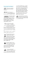
Product serial number. The serial number label is located on the top cover of the module. The serial
number can also be read from the Soft Front Panel interface, but only after the hardware is installed.

l

Description of failure or service required.

4. Pack the module in its original ESD bag and packing carton. If the original carton is not available, use bubble

wrap or packing peanuts and place the instrument in a sealed container and mark the container “FRAGILE”.

5. On the shipping label, write ATTENTION REPAIR DEPARTMENT and the RMA number.

If any correspondence is required, refer to the product by serial number and model number.

Step 2: Verify U5309A Shipment Contents

The following items are also included with your U5309A PCIe High-Speed Digitizer order:

Part Number

Quantity Description

U5309A

1

PCIe High-Speed Digitizer.

U1092-80001

1

Coaxial cable, MMCX to BNC, 1 m.

8121-2531

1

Auxiliary power cable, 4-Pin Male to Female 4-Conductor Floppy.

8121-2533

1

Auxiliary power cable, 15-Pin SATA Power Male to Power 4-Pin Floppy.

M9700-10001

1

Agilent MD2 High-Speed Digitizer Software & Product Information CD

E2094-60003

1

Agilent IO Libraries Suite CD.

U5309-90001

1

U5309A Startup Guide in hard copy.

5962-0476

1

Certificate of Calibration.

5959-4660

1

Recommended Due Date for Adjustment/Calibration.

9320-6741

1

ROHS (China addendum).

All the files contained on the CDs are available for download at

www.agilent.com/find/U5309A

.

10

U5309A Startup Guide

Содержание U5309A

Страница 1: ...Agilent Technologies PCIe High Speed Digitizer 2 or 8 channels 8 bit up to 2 GS s DC up to 500 MHz bandwidth with custom firmware support suited for embedded OEM applications U5309A Startup Guide...

Страница 2: ...or contract clause Use duplication or disclosure of Software is subject to Agilent Technologies standard commercial license terms and non DOD Departments and Agencies of the U S Government will recei...

Страница 3: ...the voltage being measured The instrument and accessories must be used in accordance with its specifications and operating instructions or the safety of the equipment may be impaired Do not exceed th...

Страница 4: ...rated from normal waste for disposal Reference WEEE Directive 2002 96 EC This symbol indicates the time period during which no hazardous or toxic substance elements are expected to leak or deteriorate...

Страница 5: ...ESD Precautions 9 Inspect for Damage 9 Return a Module for Service 9 Step 2 Verify U5309A Shipment Contents 10 Step 3 Install the Software 11 System Requirements 11 Hardware Requirements 11 Step 4 In...

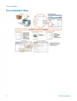
Страница 6: ...Documentation Map Documentation Map 6 U5309A Startup Guide...

Страница 7: ...your product and at www agilent com find U5309A Select Technical Support Manuals l U5309A User Manual l Help systems for the Agilent device drivers IVI C and IVI COM and LabVIEW G l Product specificat...

Страница 8: ...8 U5309A Startup Guide...

Страница 9: ...work station when working on circuitry with a voltage potential greater than 500 volts Inspect for Damage After unpacking a module inspect it for any shipping damage Report any damage to the shipping...

Страница 10: ...ial number and model number Step 2 Verify U5309A Shipment Contents The following items are also included with your U5309A PCIe High Speed Digitizer order Part Number Quantity Description U5309A 1 PCIe...

Страница 11: ...ou may not need this amount of available disk space Hardware Requirements A PC running one of the above operating systems Recommended models are HP Z420 or Dell T3610 Install the Software Agilent IO L...

Страница 12: ...e floppy drive power connector simply attach this If your PC does not have a free connector of this type you may use one of the two supplied adapters l If your PC has spare 4 pin Molex power connector...

Страница 13: ...embly in the case that two modules must be placed in adjacent slots or other PC hardware obstructs the fitting These three procedures are detailed below Fitting the module with the optional card retai...

Страница 14: ...the fan assembly 1 Remove the 4 screws B nearest to the front of the fan unit 2 Slide the fan unit approximately 15 mm to the rear until it clears the circuit board disconnect the power cables and ro...

Страница 15: ...onfigurable Input Output signal 3 3 V CMOS and TTL compatible CLK IN MMCX External clock input AC coupled and 50 terminated signal level 5 to 15 dBm Please refer to datasheet for details REF IN MMCX E...

Страница 16: ...US Module status White blinking Firmware initialization in progress Green blinking Module initialization in progress Yellow blinking Warning Red blinking Error Green OK ready Note If warning or error...

Страница 17: ...and other operational verification procedures Agilent U5309A Instrument Properties The instrument properties may be viewed by clicking on the desired instrument and then on the Instrument Properties t...

Страница 18: ...age level at the INPUT connector 3 4 V DC 1 Configure the RF Generator to produce a Sine signal with a Frequency of 1 0 MHz an Amplitude of 300 mV rms 2 55 dBm 2 Connect the Signal Generator output to...

Страница 19: ...19 U5309A Startup Guide...

Страница 20: ...iness goals increased confidence in uptime reduced cost of ownership Agilent Advantage Services www agilent com find AdvantageServices PCI Accurate measurements throughout the life of your instrument...

Отзывы: