


Service Guide E8364-90026
5-17
PNA Series Microwave Network Analyzers
Theory of Operation
E8362B, E8363B, E8364B
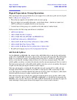
Signal Separation Group Operation
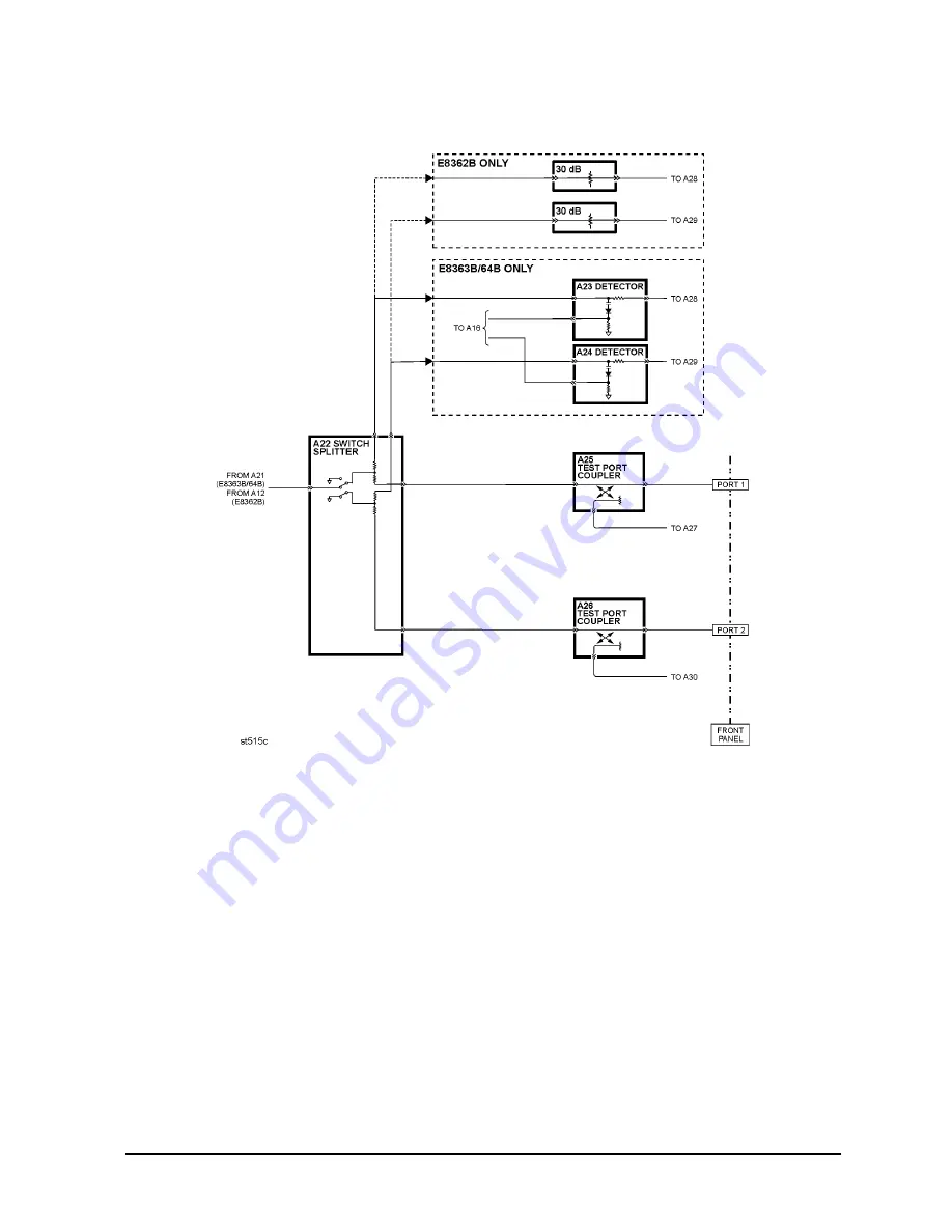
Figure 5-3 Signal Separation Group, Standard Analyzer
A25 and A26 Test Port Couplers
The test port signal goes into the through-line arm of the couplers, and from there to the
test ports and the DUT. The coupled arm of the couplers carries the signal reflected from or
transmitted through the DUT, to the receiver (through a front panel jumper for
Option 014) for measurement. The coupling coefficient of the directional couplers is
nominally 15 dB over the full frequency range.
A23 and A24 Detectors (E8363B and E8364B Only)
The A23 and A24 detectors sense the R1 and R2 reference signal levels and provide
feedback to the ALC circuitry on the A16 test set motherboard.
30-dB Fixed Attenuators (E8362B Only)
The 30-dB fixed attenuators are placed in the reference signal paths to provide isolation.
The source power output is sufficiently stable over this frequency range that ALC feedback
is not necessary.
Содержание E8362B
Страница 11: ...Service Guide E8364 90026 1 1 1 Safety and Regulatory Information ...
Страница 19: ...Service Guide E8364 90026 2 1 2 General Product Information ...
Страница 33: ...Service Guide E8364 90026 3 1 3 Tests and Adjustments ...
Страница 83: ...Service Guide E8364 90026 4 1 4 Troubleshooting ...
Страница 151: ...Service Guide E8364 90026 5 1 5 Theory of Operation ...
Страница 185: ...Service Guide E8364 90026 6 1 6 Replaceable Parts ...
Страница 269: ...Service Guide E8364 90026 7 1 7 Repair and Replacement Procedures ...
Страница 351: ...Service Guide E8364 90026 8 1 8 General Purpose Maintenance Procedures ...


