


8
Installation Note E8362-90004
Overview of the Installation Procedure
Step 1. Verify the Model, Serial, and Option Numbers of the Analyzer
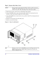
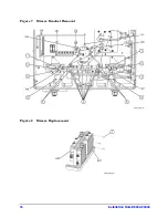
Step 2. Remove the Outer Cover
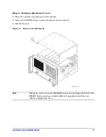
Step 3. Remove the Inner Cover
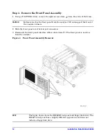
Step 4. Remove the Front Panel Assembly
Step 5. Disconnect the A12 Source 20 to A22 Switch/Splitter Cable at the A12 Source 20
Step 6. Raise the Receiver Deck
Step 7. Remove the Old Hardware and Cables
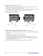
Step 8. Replace the A38 and A39 Bias Tees (Option UNL Only)
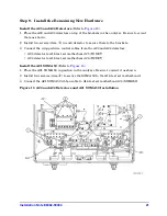
Step 9. Install the Remaining New Hardware
Step 10. Install the Remaining Cables
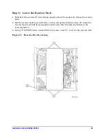
Step 11. Lower the Receiver Deck
Step 12. Connect the A12 Source 20 to A21 SOMA 50 Cable at the A12 Source 20
Step 13. Replace the Front Panel Nameplate
Step 14. Reinstall the Front Panel Assembly
Step 15. Reinstall the Inner and Outer Covers
Step 16. Enter the New Model Number
Step 17. Perform Post-Upgrade Adjustments and Calibration
Tools Required for the Installation
ESD Equipment and Supplies Required for the Installation
Description
Agilent Part Number
T-8 TORX driver (set to 5 in-lbs)
N/A
T-10 TORX driver (set to 9 in-lbs)
N/A
T-20 TORX driver (set to 21 in-lbs)
N/A
5/16-inch torque wrench (set to 10 in-lbs)
N/A
1-inch torque wrench (set to 72 in-lbs)
N/A
Description
Agilent Part Number
ESD grounding wrist strap
9300-1367
5-ft grounding cord for wrist strap
9300-0980
2 x 4 ft conductive table mat and 15-ft grounding wire
9300-0797
ESD heel strap (for use with conductive floors)
9300-1308


