


Service Guide E8364-90001
4- 35
PNA Series Microwave Network Analyzers
Troubleshooting
E8362A, E8363A, E8364A
Measurement System Troubleshooting
Node Descriptions, A8 Fractional-N Synthesizer Board
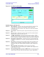
Node 411
+
5 Vdc Supply Voltage
Node 411 senses the 5 Vdc supply voltage which
serves as a measurement reference.
Node 412
1.5 to 3.0 GHz VCO Compensation
Node 412 senses the average voltage
output level of the 1.5 to 3.0 GHz VCO.
Node 413
1.5 to 3.0 GHz VCO Tune Voltage
Node 413 senses the average voltage
input level of the 1.5 to 3.0 GHz VCO.
Node 414
Heterodyne Band ALC Level
Node 414 senses the ALC output voltage
which is used to level the heterodyne circuit output for band 1.
Node 415
2.250 GHz VCO Tune Voltage
Node 415 senses the average voltage input
level of the 2.250 GHz VCO.
Node 416
Fundamental and Divide-by-2 Band ALC Level
Node 416 senses the
ALC output voltage which is used to level the heterodyne circuit output for
bands 2-25.
Node 417
2.250 GHz VCO Compensation
Node 417 senses the average voltage
output level of the 2.250 GHz VCO.
Node 418
ALC Level Adjust
Node 418 senses the voltage which is used to set the
offset on the heterodyne band ALC.
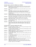
Node Descriptions, A16 Test Set Motherboard, MA 20
Node 511
ALC Output
Node 511 senses the output of the ALC integrator. The
output of the integrator is the combined voltage output of the compensation
circuits in the ALC.
Node 512
Power DAC
Node 512 senses the output voltage of the power DAC. This
output is summed with other compensation signals to control the SOMA 50
output level. The power DAC has the most influence of the compensation
signals.
Node 513
ALC Output
Node 513 senses the output of the ALC summing junction.
The output of the ALC summing junction is the combined voltage output of
all compensation circuits in the ALC. The voltage level varies with frequency
and output power.
Node 514
1V/GHz Compensation
Node 514 senses the output voltage of the
1V/GHz compensation amplifier for the LO ALC.
Node 515
Slope Compensation
Node 515 senses the slope compensation.
Node 516
−
15 V Reference
Node 516 senses the
−
15 Vdc supply voltage which
serves as a measurement reference.
Node 517
+
9 V Reference
Node 517 senses the
+
9 Vdc supply voltage which serves
as a measurement reference.
Node 518
+
15 V Reference
Node 518 senses the
+
15 Vdc supply voltage which
serves as a measurement reference.
Содержание E8362A
Страница 11: ...Service Guide E8364 90001 1 1 1 Safety and Regulatory Information ...
Страница 19: ...Service Guide E8364 90001 2 1 2 General Product Information ...
Страница 29: ...Service Guide E8364 90001 3 1 3 Tests and Adjustments ...
Страница 79: ...Service Guide E8364 90001 4 1 4 Troubleshooting ...
Страница 139: ...Service Guide E8364 90001 5 1 5 Theory of Operation ...
Страница 169: ...Service Guide E8364 90001 6 1 6 Replaceable Parts ...
Страница 215: ...Service Guide E8364 90001 7 1 7 Repair and Replacement Procedures ...
Страница 287: ...Service Guide E8364 90001 A 1 A Error Terms ...
Страница 302: ...A 16 Service Guide E8364 90001 Error Terms PNA Series Microwave Network Analyzers Error Term Data E8362A E8363A E8364A ...
Страница 303: ...Service Guide E8364 90001 B 1 B Option Enable Utility ...
Страница 309: ...Service Guide E8364 90001 C 1 C Firmware Upgrades ...
Страница 313: ...Service Guide E8364 90001 D 1 D Operating System Recovery ...


