


E2730A VXI RF TUNER
2-8
INSTALLATION
2.3 POWER AND COOLING REQUIREMENTS VERSUS MAINFRAME SELECTION
Three major factors must be considered when selecting a mainframe for a
VXI system: module size, power requirements, and cooling requirements.
The E2730A is mechanically designed as a C-size VXI module.
Therefore, a mainframe capable of housing C-size modules is required for
use with the E2730A .
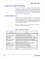
The power and cooling requirements of a mainframe are driven by the type
and number of modules installed in it. Each module has its own specific
power and cooling requirements. Thus the combination of all modules
identifies the mainframe requirement. The user should refer to the VXIbus
Specification paragraph B.7 and B.8 for information on VXI
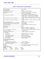
environmental considerations and power requirements. The following are
the specific power and cooling requirements for the E2730A :
DC
Volts
DC
Current
Dynamic
Current
Cooling
+5 V
+12 V
-12 V
-5.2 V
+24 V
-24 V
-2 V
2.2 A
860 mA
110 mA
400 mA
50 mA
0 A
30 mA
50 mA
150 mA
100 mA
60 mA
50 mA
0 A
0 A
0
°
C to 50
°
C Operating Ambient
Temperature
1.6 mm H
2
O Backpressure
3.0 L/S Air Flow
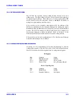
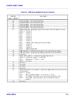
2.4 SETTING THE E2730A 's LOGICAL ADDRESS
All modules in a VXI system must be assigned a logical address to allow
controller to device communications. The E2730A is assigned a logical
address via either of two methods: Dynamic Configuration (DC) or Static
Configuration (SC). Refer to Section F in the VXIbus specification for
details on these configurations.
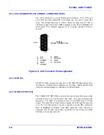
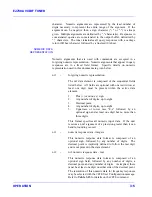
The tuner is set to either DC or SC configurations by a DIP switch located
on the Digital Control Assembly (A1). The DIP switch is accessible
through a hole in the Digital Control (DC) cover on the left side of the
tuner as shown in
Figure 2-3.
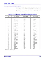
The DC configuration is selected by setting
all switch positions of the switch to OFF for a value of 255. This is the
default switch setting of the E2730A when shipped. Any other
combination of switch settings places the tuner in the SC configuration,
with its address being the decimal equivalent of the binary value of the
switch positions (ON = logic 0, OFF = logic 1).
Figure 2-3
provides the
combination of switch position settings required for various addresses.
When the E2730A is configured as a DC device, the Resource Manager
assigns a logical address to it during the power-on sequence. When the
tuner is in the SC configuration, it responds to controller commands only
after receiving the address as identified by the DIP switch.
Содержание E2730A
Страница 5: ...E2730A VXI RF TUNER iv LIST OF EFFECTIVE PAGES THIS PAGE INTENTIONALLY LEFT BLANK ...
Страница 7: ...E2730A VXI RF TUNER vi REVISION RECORD THIS PAGE INTENTIONALLY LEFT BLANK ...
Страница 12: ...1 i SECTION 1 GENERAL DESCRIPTION ...
Страница 13: ...1 ii THIS PAGE INTENTIONALLY LEFT BLANK ...
Страница 18: ...2 i SECTION 2 INSTALLATION ...
Страница 19: ...2 ii THIS PAGE INTENTIONALLY LEFT BLANK ...
Страница 32: ...3 i SECTION 3 OPERATION ...
Страница 33: ...3 ii THIS PAGE INTENTIONALLY LEFT BLANK ...
Страница 66: ...4 i SECTION 4 REPLACEMENT PARTS LIST ...
Страница 67: ...4 ii THIS PAGE INTENTIONALLY LEFT BLANK ...
Страница 71: ...E2730A VXI RF TUNER 4 4 REPLACEMENT PARTS LIST NOTES ...
Страница 72: ...FP i FOLDOUTS ...
Страница 73: ...FP ii THIS PAGE INTENTIONALLY LEFT BLANK ...


