287
Chapter 7 Plug-in Modules
Terminals and Connections Information
4
7
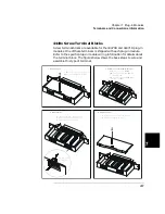
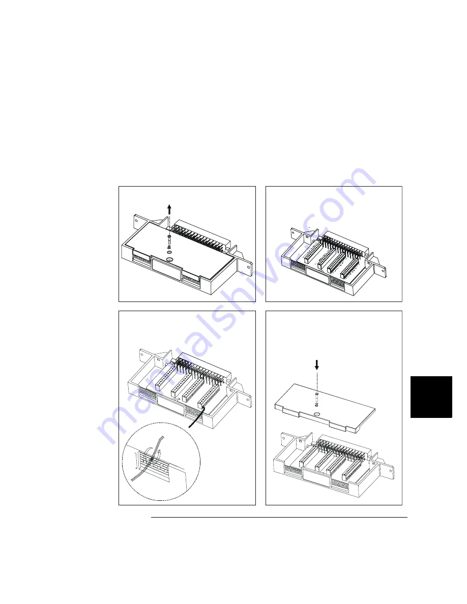
4448x Screw Terminal Blocks
Screw terminal blocks are available for the 44470D and 44471D plug-in
modules. One of these terminals is shipped with each plug-in module.
Refer to the specific plug-in module wiring information for details about
the terminal block. The figures below shows the basic steps to wire and
assemble this type of terminal.
1. Remove cover
2. Determine the wires& the wire exit
P101
P102
P103
P104
J101
EXIT 1#
EXIT 2#
B. Wires connected to P101 & P102
exit from EXIT#1;
C. Wires connected to P103 & P104
exit from EXIT# 2.
3. Attach wires
A. Insert wire into terminal connectors;
B. Tighten screws on the connectors;
C. Tighten wraps to secure wires.
Tighten wraps to
secure wires
4. Replace cover
A. Hook the top cover tabs onto the fixture;
B. Press down and tighten screw.
A. Release screw on top of the cover;
B. Press tab forward and release.
A. The wire gauge: 18-26 AWG;
Содержание Agilent 3499A
Страница 13: ...1 1 Quick Start ...
Страница 27: ...2 2 Front Panel Operation ...
Страница 55: ...3 3 System Overview ...
Страница 77: ...4 4 Features and Functions ...
Страница 113: ...5 5 Remote Interface Reference ...
Страница 164: ...164 5 ...
Страница 165: ...6 6 Error Messages ...
Страница 173: ...7 7 Plug in Modules ...
Страница 256: ...256 Chapter 7 Plug in Modules 44475A Breadboard Module 7 ...
Страница 261: ...261 Chapter 7 Plug in Modules 44476B Microwave Switch Module 4 7 The 44476B is shown below ...
Страница 268: ...268 Chapter 7 Plug in Modules 44478A B 1 3 GHz Dual 4 to 1 MUX Modules 7 The 44478A B is shown below ...
Страница 286: ...286 Chapter 7 Plug in Modules Terminals and Connections Information 7 ...
Страница 288: ...288 7 ...
Страница 289: ...8 8 Application Programs ...
Страница 299: ...9 9 Specifications ...
Страница 343: ...343 Chapter 9 Specifications 44475A Breadboard Module 4 9 ...


