270
Chapter 7 Plug-in Modules
44478A/B 1.3 GHz Dual 4-to-1 MUX Modules
7
44478A Wiring Information
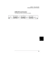
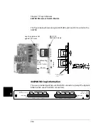
External Wiring The figure below shows the module’s female BNC
connectors and the channel group numbers. The BNC connectors accept
user-supplied male BNC connectors.
Terminations The figure on page 268 shows the SMB connectors on the
main PC Board. The SMB connectors allow you to connect SMB resistive
terminations to any unused channels. SMB resistive terminations are
available from Agilent using the following part number:
•
34585A (set of four 50
Ω
terminations for the 44478A)
•
34586A (set of four 75
Ω
terminations for the 44478B)
Note
To maintain proper operation, unused channels should be terminated by
plugging a 50
Ω
or 75
Ω
SMB type resistive termination (50
Ω
for 44478A
and 75
Ω
for 44478B) onto the male SMB connector provided for each
channel.
C
HA
NNEL
00
C
HA
NNEL
03
C
HA
NNEL
02
COM
M
O
N
00
C
HA
NNEL
01
C
HA
NNEL
10
C
HA
NNEL
13
C
HA
NNEL
12
COM
M
O
N
10
C
HA
NNEL
11
Group 00
Group 10
00
01 C OM00 02
03
10
11 C OM10 12
13
44478 MULTIPLEXER
Содержание Agilent 3499A
Страница 13: ...1 1 Quick Start ...
Страница 27: ...2 2 Front Panel Operation ...
Страница 55: ...3 3 System Overview ...
Страница 77: ...4 4 Features and Functions ...
Страница 113: ...5 5 Remote Interface Reference ...
Страница 164: ...164 5 ...
Страница 165: ...6 6 Error Messages ...
Страница 173: ...7 7 Plug in Modules ...
Страница 256: ...256 Chapter 7 Plug in Modules 44475A Breadboard Module 7 ...
Страница 261: ...261 Chapter 7 Plug in Modules 44476B Microwave Switch Module 4 7 The 44476B is shown below ...
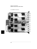
Страница 268: ...268 Chapter 7 Plug in Modules 44478A B 1 3 GHz Dual 4 to 1 MUX Modules 7 The 44478A B is shown below ...
Страница 286: ...286 Chapter 7 Plug in Modules Terminals and Connections Information 7 ...
Страница 288: ...288 7 ...
Страница 289: ...8 8 Application Programs ...
Страница 299: ...9 9 Specifications ...
Страница 343: ...343 Chapter 9 Specifications 44475A Breadboard Module 4 9 ...


