


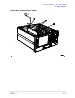


14-30
Chapter 14
Assembly Replacement and Post-Repair Procedures
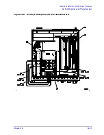
A17 Motherboard Assembly
A17 Motherboard Assembly
Tools Required
• T-10 TORX screwdriver
• T-15 TORX screwdriver
• T-20 TORX screwdriver
• small slot screwdriver
• 2.5-mm hex-key driver
• 5/16-inch open-end torque wrench (set to 10 in-lb)
• ESD (electrostatic discharge) grounding wrist strap
Removal
To remove the A17 motherboard assembly only, perform the following steps to remove all
assemblies and cables that connect to the motherboard.
1. Disconnect the power cord and remove the top, bottom, and side covers (refer to
2. Remove the front panel assembly (refer to
“Front Panel Assembly” on page 14-8
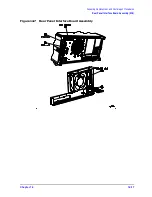
3. Remove the rear panel assembly (refer to
“Rear Panel Assembly” on page 14-14
4. Remove the preregulator (refer to
“A15 Preregulator” on page 14-28
5. Remove the graphics processor (refer to
“A19 Graphics Processor” on page 14-34
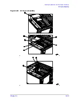
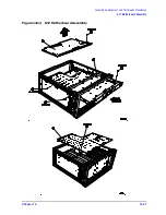
6. Remove the test set deck (item 3) by removing the three screws (item 4) from the bottom
and four screws (item 5) from the side frames. For clarity, the figure on the next page
does not show the assemblies attached to the test set deck.
7. Remove the CPU board (refer to
8. Refer to
. Remove the memory deck (item 1) by removing three screws
(item 2) from the bottom and four screws (item 6) from the side frames.
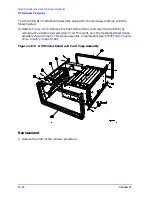
9. Remove the source assembly (refer to
“A3 Source Assembly” on page 14-18
10.Remove the samplers and pulse generator (refer to
“A4, A5, A6 Samplers and A7 Pulse
11.Remove the card cage boards (refer to
“A8, A10, A11, A12, A13, A14 Card Cage Boards”
). Continue with step 12 to remove the motherboard only, or to step 13 to
remove the motherboard/card cage assembly.
12.To disconnect the motherboard (item 7), remove the 34 riv screws (item 8). Important:
Do not misplace any of these screws.
Содержание 8753ES
Страница 14: ...Contents xiv Contents ...
Страница 15: ...1 1 1 Service Equipment and Analyzer Options ...
Страница 26: ...1 12 Chapter1 Service Equipment and Analyzer Options Service and Support Options ...
Страница 27: ...2 1 2 System Verification and Performance Tests ...
Страница 202: ...2 176 Chapter2 System Verification and Performance Tests Agilent 8753ET Performance Test Records ...
Страница 203: ...3 1 3 Adjustments and Correction Constants ...
Страница 262: ...3 60 Chapter3 Adjustments and Correction Constants Sequences for Mechanical Adjustments ...
Страница 263: ...4 1 4 Start Troubleshooting Here ...
Страница 297: ...5 1 5 Power Supply Troubleshooting ...
Страница 305: ...Chapter 5 5 9 Power Supply Troubleshooting If the Red LED of the A15 Is ON Figure 5 5 Power Supply Cable Locations ...
Страница 317: ......
Страница 318: ...6 1 6 Digital Control Troubleshooting ...
Страница 337: ...6 20 Chapter6 Digital Control Troubleshooting GPIB Failures ...
Страница 338: ...7 1 7 Source Troubleshooting ...
Страница 369: ...7 32 Chapter7 Source Troubleshooting Source Group Troubleshooting Appendix ...
Страница 370: ...8 1 8 Receiver Troubleshooting ...
Страница 381: ...8 12 Chapter8 Receiver Troubleshooting Troubleshooting When One or More Inputs Look Good ...
Страница 382: ...9 1 9 Accessories Troubleshooting ...
Страница 389: ...9 8 Chapter9 Accessories Troubleshooting Inspect the Error Terms ...
Страница 390: ...10 1 10 Service Key Menus and Error Messages ...
Страница 439: ...10 50 Chapter10 Service Key Menus and Error Messages Error Messages ...
Страница 440: ...11 1 11 Error Terms ...
Страница 451: ...11 12 Chapter11 Error Terms Error Correction ...
Страница 452: ...12 1 12 Theory of Operation ...
Страница 461: ...12 10 Chapter12 Theory of Operation Digital Control Theory Figure 12 3 Digital Control Group Simplified Block Diagram ...
Страница 482: ...13 1 13 Replaceable Parts ...
Страница 487: ...13 6 Chapter13 Replaceable Parts Ordering Information Figure 13 1 Module Exchange Procedure ...
Страница 490: ...Chapter 13 13 9 Replaceable Parts Replaceable Part Listings This page intentionally left blank ...
Страница 492: ...Chapter 13 13 11 Replaceable Parts Replaceable Part Listings Figure 13 2 8753ET Major Assemblies Top ...
Страница 494: ...Chapter 13 13 13 Replaceable Parts Replaceable Part Listings Figure 13 3 8753ES Major Assemblies Top ...
Страница 498: ...Chapter 13 13 17 Replaceable Parts Replaceable Part Listings This page intentionally left blank ...
Страница 500: ...Chapter 13 13 19 Replaceable Parts Replaceable Part Listings Figure 13 7 8753ET Cables Top ...
Страница 502: ...Chapter 13 13 21 Replaceable Parts Replaceable Part Listings Figure 13 8 8753ES Cables Top ...
Страница 504: ...Chapter 13 13 23 Replaceable Parts Replaceable Part Listings This page intentionally left blank ...
Страница 506: ...Chapter 13 13 25 Replaceable Parts Replaceable Part Listings Figure 13 10 8753ET Cables Bottom ...
Страница 508: ...Chapter 13 13 27 Replaceable Parts Replaceable Part Listings Figure 13 11 8753ES Cables Bottom ...
Страница 510: ...Chapter 13 13 29 Replaceable Parts Replaceable Part Listings Figure 13 12 8753ET Cables Front 8753ET Option 004 ...
Страница 512: ...Chapter 13 13 31 Replaceable Parts Replaceable Part Listings Figure 13 13 8753ES Cables Front ...
Страница 514: ...Chapter 13 13 33 Replaceable Parts Replaceable Part Listings Figure 13 14 8753ET ES Cables Rear ...
Страница 518: ...Chapter 13 13 37 Replaceable Parts Replaceable Part Listings Figure 13 17 8753ET ES Front Panel Assembly Outside ...
Страница 520: ...Chapter 13 13 39 Replaceable Parts Replaceable Part Listings Figure 13 18 8753ET ES Front Panel Assembly Inside ...
Страница 522: ...Chapter 13 13 41 Replaceable Parts Replaceable Part Listings Figure 13 19 8753ET Rear Panel Assembly ...
Страница 524: ...Chapter 13 13 43 Replaceable Parts Replaceable Part Listings Figure 13 20 8753ES Rear Panel Assembly ...
Страница 526: ...Chapter 13 13 45 Replaceable Parts Replaceable Part Listings Figure 13 21 8753ET ES Rear Panel Assembly Option 1D5 ...
Страница 528: ...Chapter 13 13 47 Replaceable Parts Replaceable Part Listings Figure 13 22 8753ET ES Hardware Top ...
Страница 538: ...Chapter 13 13 57 Replaceable Parts Replaceable Part Listings Figure 13 31 8753ET ES Chassis Parts Outside ...
Страница 544: ...14 1 14 Assembly Replacement and Post Repair Procedures ...
Страница 550: ...Chapter 14 14 7 Assembly Replacement and Post Repair Procedures Covers Figure 14 2 Covers ...
Страница 552: ...Chapter 14 14 9 Assembly Replacement and Post Repair Procedures Front Panel Assembly Figure 14 3 Front Panel Assembly ...
Страница 558: ...Chapter 14 14 15 Assembly Replacement and Post Repair Procedures Rear Panel Assembly Figure 14 6 Rear Panel Assembly ...
Страница 562: ...Chapter 14 14 19 Assembly Replacement and Post Repair Procedures A3 Source Assembly Figure 14 8 A3 Source Assembly ...
Страница 568: ...Chapter 14 14 25 Assembly Replacement and Post Repair Procedures A9 CPU Board Figure 14 11 A9 CPU Board ...
Страница 570: ...Chapter 14 14 27 Assembly Replacement and Post Repair Procedures A9BT1 Battery Figure 14 12 A9BT1 Battery ...
Страница 572: ...Chapter 14 14 29 Assembly Replacement and Post Repair Procedures A15 Preregulator Figure 14 13 A15 Preregulator ...
Страница 588: ...Chapter 14 14 45 Assembly Replacement and Post Repair Procedures A23 LED Board 8753ES Only Figure 14 20 A23 LED Board ...
Страница 597: ...14 54 Chapter14 Assembly Replacement and Post Repair Procedures Post Repair Procedures ...
Страница 598: ...15 1 15 Safety and Regulatory Information ...


