


5-30
Servicing
Replacing Instrument Assemblies
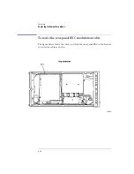
To replace the A5 Laser Driver Board Assembly
Three resistors on the A5 Laser Driver Board Assembly limit the maximum
current to the A2A3 Pump Laser. These resistors are matched to the particu-
lar pump laser installed in your instrument. New A5 assemblies are shipped
with these three resistors unloaded. You must load new resistors, which match
the values loaded in the original A5 assembly, into the new A5 assembly. A bag
of resistors is supplied with the new assembly. Refer to “Major Assemblies” on
page 5-37 for the part number of the A5 replacement assembly.
W A R N I N G
Failure to load the proper resistor values as described in this
procedure could destroy the laser or result in increased laser output
power from the front-panel
OPTICAL OUT
connector. Increased laser
output power may change the laser classification of the product.
1
Remove the A5 Laser Driver Board Assembly from the instrument.
2
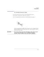
Locate resistors R2, R8, and R9 as shown on the following diagram.
3
Read the values of each of these three resistors, and write them down. The
values should be printed on the sides of each resistor.
The possible values of each of resistors is 82
Ω
, 100
Ω
, 125
Ω
, or 150
Ω
. In the cir-
cuit, they are wired in parallel.
4
Locate the bag of resistors that was shipped with the new A5 Laser Driver
Board Assembly. Find three resistors with identical values to those identified
in the previous step.
5
Solder these resistors into the new A5 Laser Driver Board Assembly.
6
Installed the new assembly into the instrument.
7
Use an optical power meter to confirm that the total output power emitted from
the front-panel
OPTICAL OUT
connector does not exceed the following limits:
Maximum: +8.1 dBm (6.5 mW)
Minimum: +5.5 dBm (3.5 mW)
Maximum: +5.1 dBm (3.2 mW) (Option 009)
Minimum: +2.5 dBm (1.8 mW) (Option 009)
Содержание 83437A
Страница 1: ...Agilent 83438A Erbium ASE Source User s Guide ...
Страница 5: ...v The Agilent 83438A At a Glance Rear view of instrument ...
Страница 8: ......
Страница 10: ......
Страница 24: ...2 4 Making Measurements Performing Stimulus Response Measurements ...
Страница 41: ...3 Specifications 3 3 Regulatory Information 3 6 Specifications and Regulatory Information ...
Страница 47: ...3 7 Specifications and Regulatory Information Regulatory Information Declaration of Conformity I ll ...
Страница 48: ......
Страница 54: ......
Страница 61: ...5 7 Servicing General Information ...
Страница 63: ...5 9 Servicing General Information ...
Страница 79: ...5 25 Servicing Adjustment Procedure ...
Страница 85: ...5 31 Servicing Replacing Instrument Assemblies Location of resistors R2 R8 and R9 ...
Страница 92: ...5 38 Servicing Replaceable Parts ...
Страница 94: ...5 40 Servicing Replaceable Parts ...
Страница 96: ...5 42 Servicing Replaceable Parts ...
Страница 98: ...5 44 Servicing Replaceable Parts ...
Страница 100: ...5 46 Servicing Replaceable Parts ...
Страница 106: ......