


5-18
Servicing
Troubleshooting
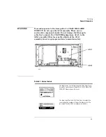
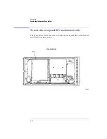
To check the A4 Power Supply Board Assembly
1
Check the 6.3A fuse in the rear-panel’s line module FL1. Refer to “To check the
line-power fuse” on page 5-19.
2
Remove the power supply cable from J2 on the A5 Laser Driver Board
Assembly. The end of this cable can be probed to measure all of the dc voltages
supplied in the instrument. The following list shows each wire color, its color
code, and its purpose:
• Red (2) wire: +15V
• White/red (92) wire: +5V
• Violet (7) wire: –15V
• Black (0) wire: ground
• White/black (90) wire: ground
3
If no voltages are detected, check that the ac line input voltage at the cable that
connects to J1 on the A4 Power Supply Board Assembly. Measure the line
voltage across the white/gray/red wire and the gray wire. If the ac line voltage
is present, replace the A4 Power Supply Board Assembly.
Содержание 83437A
Страница 1: ...Agilent 83438A Erbium ASE Source User s Guide ...
Страница 5: ...v The Agilent 83438A At a Glance Rear view of instrument ...
Страница 8: ......
Страница 10: ......
Страница 24: ...2 4 Making Measurements Performing Stimulus Response Measurements ...
Страница 41: ...3 Specifications 3 3 Regulatory Information 3 6 Specifications and Regulatory Information ...
Страница 47: ...3 7 Specifications and Regulatory Information Regulatory Information Declaration of Conformity I ll ...
Страница 48: ......
Страница 54: ......
Страница 61: ...5 7 Servicing General Information ...
Страница 63: ...5 9 Servicing General Information ...
Страница 79: ...5 25 Servicing Adjustment Procedure ...
Страница 85: ...5 31 Servicing Replacing Instrument Assemblies Location of resistors R2 R8 and R9 ...
Страница 92: ...5 38 Servicing Replaceable Parts ...
Страница 94: ...5 40 Servicing Replaceable Parts ...
Страница 96: ...5 42 Servicing Replaceable Parts ...
Страница 98: ...5 44 Servicing Replaceable Parts ...
Страница 100: ...5 46 Servicing Replaceable Parts ...
Страница 106: ......