background image

Setting up a proprietary System

Display Control Panel

34

Display Control Panel 

If the display and entry panel, Option 001, is used then the display resolution is automatically adjusted 
to 640 x 480.

It is possible to have in parallel a monitor connected. To use the higher resolution of the monitor it is 
possible to switch either to monitor (CRT) only or parallel use of CRT and display & entry panel 
(Panel)

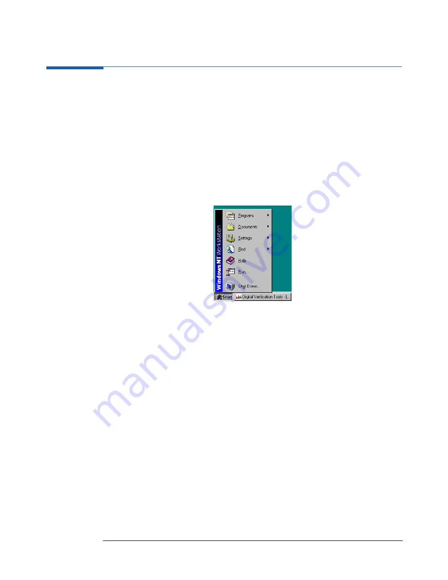
To control the display mode perform the following steps

1. Click on Start in the task bar.

Figure 27

Click Start in the Task Bar then click Shut Down

2. Point on Settings and click on Control Panel.

Содержание 81200

Страница 1: ...Agilent 81200 System Installation Guide ...

Страница 2: ... product is a Safety Class 1 instrument provided with a protective earth terminal The protective features of this product may be impaired if it is used in a manner not specified in the operation instructions All Light Emitting Diodes LEDs used in this product are Class 1 LEDs as per IEC 60825 1 Environmental Conditions This instrument is intended for indoor use in an installation category II pollu...

Страница 3: ...3 ...

Страница 4: ...4 ...

Страница 5: ... up an Agilent 81200 System based on Agilent E4849B C Mainframe 20 Connecting external peripherals 21 Apply AC Line Voltage to the Agilent 81200 System 23 Next Step 23 Setting up an Extended Agilent 81200 System based on Agilent E4849B C and Agilent E4848B Mainframes 24 Connecting external peripherals 25 MXI VXI and INTX Interconnection 26 Clock Reference Interconnection 29 Apply AC Line Voltage t...

Страница 6: ...Display 44 How to Set the Resolution of a CRT Display 44 Select the System Operating Mode 46 Select Auto Start Option 47 Build your System 47 Define your I O Interface 47 How to Start the Agilent 81200 User Software 48 Getting Help 48 How to Test your System 49 Chapter 5 Software Installation Update 51 Installing Updating the Agilent E4873A User Software 52 Prerequisites 52 Installation Procedure ...

Страница 7: ...ng a CD ROM Drive to the Agilent 81200 System 61 Connecting a Local Printer to the Agilent 81200 System 63 Installing a Local Printer 64 Installing a Network Printer 66 Connecting the Agilent 81200 System to LAN 67 Receiving Administrator Privileges 67 Configuring the Agilent 81200 System for LAN Connection 68 ...

Страница 8: ...8 ...

Страница 9: ...a small amount of activities is required to get this system up and running 2 The modules of the Agilent 81200 system can be combined with other VXI modules to build an open VXI system Due to the flexibility of that solution a different set of activities must be done to integrate these modules into a new or existing VXI system In addition during system installation you must take care of the other s...

Страница 10: ... list to determine your system configuration than follow the setting up instructions provided for that system type Factory pre installed as a proprietary system the Agilent 81200 System has the following major configurations Based on the 3 slot small mainframe Agilent E4840A see setup instructions Setting up an Agilent 81200 System based on E4840A Small Mainframe on page 16 Based on the 10 slot ma...

Страница 11: ... printing features The User Guide provides a system introduction and how to use the features and functions The Programming Reference gives an programming overview and a complete reference to SCPI commands for remote control of the instrument The System Specification summarizes the specification for all components available for the Agilent 81200 System To verify the warranted performance of this sy...

Страница 12: ...Getting Started Steps to Get Started 12 ...

Страница 13: ...ration you have ordered and received then go to the section mentioned and perform the steps to set up the Agilent 81200 System from the components you have received The Agilent 81200 System has the following major configurations Based on the 3 slot small mainframe Agilent E4840A see setup instructions Setting up an Agilent 81200 System based on E4840A Small Mainframe on page 16 Based on the 10 slo...

Страница 14: ...Setting up an Agilent 81200 System based on E4840A Small Mainframe on page 16 Figure 1 Small and Economical System Configuration The Medium System Configuration If you have received one 13 slot mainframe like the following then go to Setting up an Agilent 81200 System based on Agilent E4849B C Mainframe on page 20 Figure 2 Medium System Configuration ...

Страница 15: ...stem Configuration If you have received two or three 13 slot mainframes like the following then go to Setting up an Extended Agilent 81200 System based on Agilent E4849B C and Agilent E4848B Mainframes on page 24 Figure 3 Extended System Configuration ...

Страница 16: ...ilent 81200 System to rain or other excessive moisture Protect the Agilent 81200 System from humidity and temperature changes which could cause condensation within the instrument The systems comes along with all cable connections possible to do at the factory Nevertheless it is recommended to check these connections as they can get loose during transportation 1 Check that all generator analyzer mo...

Страница 17: ...le with the label Touchpad to the connector on the front panel of the mainframe with the mouse symbol 3 The third cable has to be connected to the connector named DISPLAY ENTRY on the front panel Figure 5 Option 001 Connections on the Front Panel Figure 6 Option 001 connected to a standard Agilent E4840A small mainframe ...

Страница 18: ...onitor Keyboard and Mouse are not supplied as part of the Agilent 81200 Data Generator and Analyzer System 1 Connect the video cable of the monitor to the video in connector of the mainframe this connector is on the right side of the mainframe 2 Connect the keyboard cable to the connector with the keyboard symbol on the mainframe front panel 3 Connect the mouse cable to the connector with the mous...

Страница 19: ...pply AC Line Voltage to the Agilent 81200 System Connect the power cord delivered to the line in connector at the rear panel of the mainframe Connect the other end of the power cord to an AC Line Voltage outlet which provides the required power Next Step After making all the required connections the system can be started go to Start the System on page 43 Connect Monitor Video Cable here ...

Страница 20: ...reading it In addition there is in minimum one module installed the Agilent E4831A the Clock and Data Generator module It is possible to add up to nine Agilent E4841A or E4861A modules to this systems To have a maximum of nine modules working in this mainframe it is necessary to have the Agilent E4805A Central Clock module instead of the Agilent E4831A Clock and Data Generator Module Figure 9 A ty...

Страница 21: ...her an optional available display and entry panel Option 001 or a monitor keyboard and mouse A Connecting the Option 001 Display and Entry Panel On the Display and Entry Panel there are three cables One cable has the label Keyboard another cable has the label Touchpad and the third cable is the display cable 1 Connect the cable with the label Keyboard to the connector on the front panel of the mai...

Страница 22: ...System Setting up an Agilent 81200 System based on Agilent E4849B C Mainframe 22 Figure 11 Option 001 Connections on the Front Panel of the 3 slot Controller Figure 12 Option 001 connected to a standard Agilent E4849A mainframe ...

Страница 23: ...pply AC Line Voltage to the Agilent 81200 System 1 Check that the mainframe is set to the appropriate voltage range required in your country The voltage range selector is located at the rear panel Usually the mainframes leave the factory prepared for the correct voltage range for the country of destination 2 Connect all mainframes and all peripherals which require line voltage to the ac line volta...

Страница 24: ...n installation guide is also part of the shipment you are actually reading it Each of the Agilent E4848B and Agilent E4849B C mainframes contain one Agilent E1482B MXI Interface card and one Agilent E4805A Central Clock module So it is possible to add up to eight modules in the Agilent E4849B C mainframe and up to eleven modules in each of the extender frames to this systems Figure 14 A typical Ex...

Страница 25: ...nnections in all Mainframes Connecting external peripherals It is recommended to use monitor keyboard and mouse with the extended system only Connecting a monitor keyboard and mouse to the system If you have not ordered a display and entry panel option 001 the following devices are required Super VGA monitor Keyboard with PS2 connector Mouse with PS2 connector NOTE Monitor Keyboard and Mouse are n...

Страница 26: ...t E1482B MXI Interface Card Use the delivered MXI cables to connect from one Agilent E1482B card in one mainframe to the other Agilent E1482B card in the other mainframe Up to two additional mainframes can be connected Figure 17 Recommended Positioning of Master and Slave Mainframes in a typical Extended Agilent 81200 System based on Agilent E4849B C Mainframe and two Extender Frames Mouse Keyboar...

Страница 27: ...t the MXI and INTX Extender cables connectors where only single connection can be made to the Agilent E1482B card in the Master mainframe see Figure Figure 18 MXI VXI Interconnection of the Extended Agilent 81200 System Connect the MXI and INTX cable to the Agilent E1482B card in the Master Mainframe MXI cable INTX cable is below the MXI cable ...

Страница 28: ...em 3 Connect the second set of MXI and INTX cables on top of the connectors of the cables coming from Master Mainframe see Figure above 4 Connect the other end of the second MXI and INTX cable set coming from the Extender 1 to the Agilent E1482B card in the Extender 2 Mainframe see previous figure Connect the MXI and INTX cable to the Agilent E1482B card in the Extender 1 Mainframe MXI cable comin...

Страница 29: ...tional mainframes can be connected It is necessary to unplug the Agilent E4805A Central Clock Module from the Master mainframe open the side panel and connect the flat cable from Extender 1 and Extender 2 into the connectors on the main board of the module 1 In the Master mainframe disconnect all clock distribution cables to the Agilent E4841A or E4861A modules going from the Central Clock module ...

Страница 30: ...f the module A TORX No 362 screw driver is required Figure 21 Unscrew the 7 screws of the Agilent E4805A Clock Module to open it 5 Put the opened clock module with its front panel on top vertical in front of the racked mainframes Figure 22 Put the Clock Module in front of the racked mainframes Unscrew the 7 screws Here the TORX screw driver is required See detail in the next figure ...

Страница 31: ...t ones 5 mm The other four screws are long ones 14 mm 8 Plug in the Agilent E4805A Clock module into its place in the Master mainframe 9 Re connect all clock cables which go to the E4841A or E4861A modules in the Master mainframe 10 Now connect the two clock distribution cables which go from the Master mainframe s Agilent E4805A Clock Module Extender Connection to Extender 1 and Extender 2 mainfra...

Страница 32: ... rear panel Usually the mainframes leave the factory prepared for the correct voltage range for the country of destination 2 Connect all mainframes and all peripherals which require line voltage to the ac line voltage Connect the power cord delivered to the line in connector at the rear panel of the mainframe Connect the other end of the power cord to an AC Line Voltage outlet which provides the r...

Страница 33: ...in the right corner of the status bar at the lower right hand side corner of the display Figure 25 Touchpad Icon in the Status Bar 1 Put your finger tip onto the Touchpad Keep your finger on the Touchpad and glide your finger across the pad and watch the movement of the cursor 2 Now move the cursor to the Touchpad Icon 3 Now tap on the surface of the Touchpad this is the same as clicking the left ...

Страница 34: ...It is possible to have in parallel a monitor connected To use the higher resolution of the monitor it is possible to switch either to monitor CRT only or parallel use of CRT and display entry panel Panel To control the display mode perform the following steps 1 Click on Start in the task bar Figure 27 Click Start in the Task Bar then click Shut Down 2 Point on Settings and click on Control Panel ...

Страница 35: ...In the Control Panel window double click on WinNT Control Panel icon Figure 28 Double click on WinNT Control Panel Icon 4 In the WinNT Display Control Panel window click on the required display mode then click on Ok Figure 29 Click on the Display Mode Required ...

Страница 36: ...Setting up a proprietary System Display Control Panel 36 ...

Страница 37: ...ystem you have to differentiate between an embedded PC VXI system and an external PC VXI system Depending on this main configurations you have different choices of interfaces and where to install the User Software In both cases this PC needs to run Windows NT 4 0 Use the System Configuration Overview to identify your system and after that follow the required steps to install hardware and software ...

Страница 38: ...s based PC installed in slots 0 and 1 of a C Size VXI mainframe The interface to the Agilent 81200 modules is the VXI backplane Peripherals and additional equipment are connected to this embedded PC Figure 30 Embedded PC VXI System If you are installing the Agilent 81200 modules in such a system please proceed with Installing Agilent 81200 Modules into Embedded PC VXI Systems on page 40 ...

Страница 39: ...C VXI systems are defined to consist of an external Windows based PC and an interface between the PC and a VXI mainframe Figure 31 External PC VXI System If you are installing the Agilent 81200 modules in such a system please proceed with Installing Agilent 81200 Modules into External PC VXI Systems on page 41 ...

Страница 40: ...he PC Then install the PC in Slots 0 and 1 of the mainframe See the applicable PC User s Manual for details Be sure to observe all ESD precautions when handling installing and removing the PC 2 Connect Interface devices such as monitor keyboard mouse external CD ROM etc to the installed PC See the applicable PC User s Manual for instructions Install Agilent 81200 System Components The Agilent 8120...

Страница 41: ...t the PC to your network See your System Administrator for connection requirements Install VXI Hardware Install Mainframe s As required rack mount the mainframe s for your VXI system using the procedures in the applicable Rack Mount Installation Guide 1 Install the ground connector for 66 Hz and above operation ONLY connect the power cord and configure each mainframe as required as shown in the ap...

Страница 42: ...to install the modules Connect Interface Cable Connect one end of the interface cable to the PC I_O card you installed during configuring your PC Connect the other end of the cable to the Slot 0 Controller card If you have GP IB Rack Stack equipment in your system you can also connect the GP IB cable to the Rack Stack instruments Install Libraries and User Software 1 Install the applicable I_O Lib...

Страница 43: ...em 3 Select the kind of display you are using The display driver is set to a mode that supports both CRT and the flat panel option The resolution is 640 x 480 pixels This should always be the first step after power on Problems can arise if you operate Windows or the Agilent 81200 software without specifying your display See Select your kind of Display on page 44 for more details 4 Select the Syste...

Страница 44: ...lay 1 Double click the WinNT Control icon on the Windows desktop or in the Start Settings Control Panel 2 Activate your display from the window Figure 32 WinNT Display Control Panel Select CRT if you have connected a monitor to the controller Select Panel if you are using the Display and Entry Panel option Select CRT Panel if you are using both CRT and Display and Entry Panel The display resolutio...

Страница 45: ...ct your kind of Display 45 3 Double click Display 4 Click the Settings tab 5 Set the desired resolution 6 If you are sure that your monitor will make it click Apply If not click Test check the result and finally click Apply ...

Страница 46: ... IEEE 1394 or MXI 2 interface by an external PC Controlled Used if the hardware shall be controlled but the system shall not be operated from the built in computer The system can then be operated via GP IB or LAN The Agilent 81200 server is started Remote Used to operate a system which is in controlled mode remotely The Agilent 81200 user interface is started Changing this predefined values is rec...

Страница 47: ...tits bak NOTE Executing Build System twice will overwrite your backup files The default generated system name is DSRA If the mainframe contains more than one master clock module additional systems DSRB DSRC are automatically set up Build System must be processed due to any change in your hardware Build System is not needed if you are upgrading from a previous User Software version without changing...

Страница 48: ...ing the user interface to be on a different computer If the system is started in Remote Mode a screen pops up asking for hostname and network port number Figure 34 Agilent 81200 Start in Remote Mode Enter the computer name or the IP and the associated port of the instrument controller you would like to connect to You will find the appropriate setting on the controlled machine by opening the Agilen...

Страница 49: ...se of problems can identify defective field replaceable units System Self test Provides a window from which the complete self test or subsets can be started Ensures that all modules respond Returns the current firmware revisions of the modules and the identification numbers of installed front ends Module Self test Enables you to check all or single modules Checks the front ends built into the modu...

Страница 50: ...Start the System How to Test your System 50 ...

Страница 51: ...4840A or the Agilent E4849B C mainframes have the Agilent E4873A User Software already installed You should follow this procedure if you are upgrading from a previous version or if the Agilent 81200 System User Software Agilent E4873A needs to be installed on an other system than mentioned above ...

Страница 52: ...n and immediately afterwards the SHIFT key and keep it down until the logon window appears Change the user to Administrator and enter the administrator password DVTADM factory default 3 Check the status of your HP I O Library Execute Start Programs HP I_O Libraries I_O Config After the I O Config Application appears select in the upper main window Help About I O Config The version shown must be G ...

Страница 53: ...P IB and press Configure Set the following values SICL Interface Name hpib or any preferred name Bus Address 11 Deactivate System Controller if system should be controlled via GPIB by another controller Finish Interface Configuration with OK 8 Install the Agilent 81200 User Software Insert the Agilent 81200 User Software CD into the CD ROM drive Execute CD setup exe and follow the instructions on ...

Страница 54: ...ou are connecting the system to your local area network If the system is not connected to the LAN make sure that the network is configured as follow IP Address 192 000 000 001 Subnet Mask 255 255 255 0 Default Gateway none Domain standalone Updating the Firmware BIOS If you have upgraded from a previous version the new Agilent E4873A User Software may be incompatible with the firmware version inst...

Страница 55: ...page 56 Removing Modules on page 58 Adding the Trigger Input Pod on page 59 Connecting a CD ROM Drive to the Agilent 81200 System on page 61 Connecting a Local Printer to the Agilent 81200 System on page 63 Installing a Network Printer on page 66 Connecting the Agilent 81200 System to LAN on page 67 ...

Страница 56: ...Mainframe Overview table You should maintain such a table for each mainframe in order to keep track of the installed instruments Setting the VXI Instrument Logical Address When you have selected the slot for the VXI instrument the next step is to set the instrument logical address LADDR as required In general you can use the factory set default logical address If you need to set another logical ad...

Страница 57: ...ing the system 3 Secure the module to the mainframe with the two retaining screws on top and bottom of the front panel 4 Connect Clock Distribution Cable Build the new System After powering up the system open the Agilent 81200 Configuration Window and press the Build System button A diagnostic tool will be started which automatically updates your system configuration files If that step is not done...

Страница 58: ...ress the upper release to the top and the lower release to the bottom and pull out the module from the slot Build the new System After powering up the system open the Agilent 81200 Configuration Window and press the Build System button A diagnostic tool will be started which automatically updates your system configuration files If that step is not done the User Software will not recognize that a m...

Страница 59: ... driver Installing the Trigger Input Pod To connect the Trigger input pod it is necessary to unplug the E4805A module from the mainframe to open the module and to plug the pod cable into the board 1 Switch off the system and disconnect the power cord 2 Disconnect all cables from the E4805A B Central Clock Module If necessary mark the cables to make it easier to re connect the cables into the right...

Страница 60: ...shorter ones 7 Plug the module into the mainframe again and fasten the module 8 Re connect all cables disconnected during step 2 Figure 36 Trigger Input Pod Replacement Call the Agilent support if you need additional probe leads The required part number is16520 62102 You need to remove the leads from the probe adapter header before plugging them into the pod housing Plug this connector into the E4...

Страница 61: ...0 System 61 Connecting a CD ROM Drive to the Agilent 81200 System Figure 37 SCSI Interface of the Agilent E4840A Mainframe Figure 38 SCSI Interface of the Agilent E4849B C with 3 slot Controller Connect CD ROM Drive here Connect CD ROM Drive here ...

Страница 62: ...nd SCSI connector of the CD ROM drive 4 Connect the CD ROM Drive to the Agilent 81200 System by a 50 pin high density SCSI cable 5 Connect the CD ROM Drive to the line power and switch it on if necessary some drives are automatically powered when connected to line power 6 Now switch on the Agilent 81200 System 7 When the boot process has finished you can verify whether the CD ROM Drive was recogni...

Страница 63: ...m Connect a local printer to the Agilent 81200 System s parallel port located as shown in the figures below Figure 40 Parallel Port of the Agilent E4840A Mainframe Figure 41 Parallel Port of the Agilent E4849B C 3 slot Controller Connect a Printer with Parallel Port here Connect a Printer with Parallel Port here ...

Страница 64: ...dd Printer The Add Printer Wizard dialog box appears The default procedure is adding a local printer to My Computer Figure 43 Add Printer Wizard 3 Follow the instructions on the screen 4 During the printer setup you are asked to specify the location where the printer drivers can be found The printer drivers are located on the d drive in the i386 directory so please browse to this directory and sel...

Страница 65: ...a Local Printer to the Agilent 81200 System 65 5 When you have finish this procedure then the icon for your printer appears in the Printers folder Your printer is ready for you to use Figure 44 Local Printer Added ...

Страница 66: ...nt What you should know before installing a network printer name of the printer server in the network name of the printer in the network Please contact your system or network administrator to find out the required information 1 Click the Start button point to Settings and then click Printers The Printers folder appears 2 In the Add Printer Wizard click on Network printer server Then follow the ins...

Страница 67: ...appears 4 Click on the Yes button in the Shut Down Window 5 When the new logon dialog box is displayed you can release the Shift key again 6 In the new logon dialog box type in Administrator as the User name Enter as Password DVTADM The password is case sensitive so type it in as shown NOTE When you switch on the Agilent 81200 System the next time you will get an error dialog stating that the pass...

Страница 68: ...1200 System for LAN Connection 1 Connect a network cable to the Agilent 81200 System Figure 45 Ethernet Interface of the Agilent E4840A Figure 46 Ethernet Interface of the Agilent E4849B C with 3 slot Controller Three different LAN Connectors Three different LAN Connectors ...

Страница 69: ...meters which are IP Address 192 0 0 1 Subnet Mask 255 255 255 0 Default Gateway none Domain standalone You have to collect the necessary information you require in your network Please ask your local system or network administrator for help When you have collected all the data please follow the following steps 1 Click Start button point to Settings and then click on Control Panel 2 Double click on ...

Страница 70: ...m to LAN 70 3 To change the default Computer Name Workgroup and Domain on the Identification card click on the Change button Figure 48 Change Identification Click here to change the computer identification your_computer_name your_domain ...

Страница 71: ... changes and click OK Figure 49 Make your changes 5 Select the Protocol card and click on the Properties button to make the necessary changes to IP Address Subnet Mask and Default Gateway Figure 50 Protocol Card Click the OK button when you made your changes your_computer_name your_domain Click on Properties ...

Страница 72: ...the TCP IP Properties and click the OK button Figure 51 Make your changes to the TCP IP Properties 7 You have made all necessary changes and entries Click as often OK button to leave the Network setup Then click the button in the upper right hand side corner of the Control Panel ...

Страница 73: ...Mainframe 40 Extended System 24 Libraries and User Software 42 Mainframe 40 41 Slot 0 Card 41 Small System 16 software 52 VXI Hardware 40 41 Installation Procedure 52 Installing a Local Printer 64 Interconnection INTX 26 MXI VXI 26 L LAN Connecting 67 LAN Connection configure 68 Line Voltage apply 32 Local 46 Local Printer install 64 Login as administrator 52 M Medium System 14 Modify Your System ...

Страница 74: ...ystem Set up Installation 13 T Test your System 49 Touchpad 33 Trigger Input Pod add 59 U Update Software 51 Updating Software 52 Updating the Firmware 54 user software installation 52 W World Wide Web 2 11 ...

Страница 75: ......

Страница 76: ... Copyright Agilent Technologies 1999 2000 Edition E0800 Printed in Germany E4849 91023 ...

Отзывы: