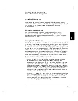
Overload Detection
The 34420A uses both an analog and digital method to generate an
overload condition and display the OVLD message. An understanding of
the cause of the overload can help you make more accurate
measurements.
Digital Overload Detection
The digital overload detect occurs when the magnitude of the
measurement is greater than 120% of the Range. For example,
on the 1 volt Range, signal levels of greater than
±
1.2 volts will cause
an OVLD in the display.
Analog Overload Detection
Another type of overload can result in measurement errors that are hard
to identify. For example if an overload signal only occurs for a portion of
the measurement period, the input amplifier could become non-linear
resulting in an inaccurate reading. The displayed result may appear to be
correct because the overload signal only occurred during a small portion
of the measurement cycle. The 34420A detects this problem by
providing comparators on the input amplifier. If signals large enough to
overload the input amplifier are detected, the display will read OVLD.
The comparators detect signals greater than 140% of the range setting.
If an overload occurs, two solutions are possible.
•
Setting the meter to the next higher range will provide 10 times
improvement in the overload signal handling capability. For
example,if you are measuring on the 1 mV range and have 2 mV rms
of power line (50 or 60 Hz) pickup, the noise overload comparators
would sense the peaks of the signals and an OVLD message would be
displayed. If you set the range to 10 mV, the resolution (with 7 digits)
is still 1 nanovolt, and the reading rate is faster than if ANALOG
FILTER had been turned on. Additionally, the 10 mV range noise is
almost as low as the 1 mV range.
•
Alternately, if using the 1 mV, 10 mV, or 100 mV ranges, turn on the
ANALOG FILTER. The reading rate slows down with the filter on. In
the case of a larger overloads (for example, 20 mV rms noise on the
1 mV range) using the ANALOG FILTER would give a lower noise
result than changing to the 100 mV range.
3
Chapter 3 Features and Functions
General Measurement Configuration
65
Содержание 34420A
Страница 1: ......
Страница 2: ......
Страница 13: ...1 Quick Start ...
Страница 31: ...2 Front Panel Operation ...
Страница 55: ...3 Features and Functions ...
Страница 117: ...4 Remote Interface Reference ...
Страница 200: ...5 Error Messages ...
Страница 213: ...6 Application Programs ...
Страница 245: ...6 Chapter 6 Application Programs Microsoft Excel Macro Example 245 ...
Страница 246: ...Chapter 6 Application Programs Microsoft Excel Macro Example 246 ...
Страница 247: ...7 Measurement Tutorial ...
Страница 274: ...8 Specifications ...
Страница 279: ...Dimensions Chapter 8 Specifications 34420A Nano Volt Micro Ohm Meter 280 ...
Страница 294: ......


