


S - 4
Set up
If you want to connect your terminals to separate
Western sockets, you will find the connection
panel for the plug-in terminals underneath the
blue cover.
Unplug the power pack from the 230 V mains
socket before removing the cover from and
working on the connection panel. Replace the
cover before plugging the power pack back into
the mains socket.
To open the connection panel,
reach underneath the blue cover
on the connection side of the
telecommunications system and
pull the cover down sharply.
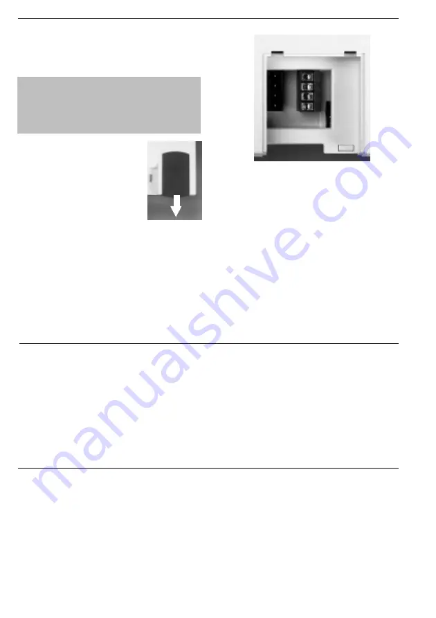
The assignment of the terminal
connections is displayed on the
connection panel.
To ensure perfect functioning of the
telecommunications system and the connected
terminals, you should connect the terminals
either to the Western sockets or the plug-in
terminals! This means that if a terminal is
connected directly via a Western socket, e.g.
connection 1, no second device should be
connected via the terminals at the same terminal
connection, e.g. La1/Lb1.
The connections La and Lb of the plug-in
terminals are connected with connections 1 and 2
of the separate Western sockets.
You can use commercially available telephone
lines for the connection.
We recommend: telephone lines J-Y (St) Y
Length between telecommunications system and
sockets: max. 800 metres at 0.6 mm wire
diameter.
To close the connection panel, place the cover flat
on the guides. Push the cover up sharply until it
snaps audibly into place.
Connecting terminals to separate TAE sockets
PC interface
The PC interface of the telecommunications
system is a serial RS 232C interface. Here you can
connect:
- a PC, for configuring the telecommunications
system, for call data evaluation and computer-
aided telephony (CTI). The PC connecting cable
is contained in the scope of delivery.
Terminal 3
Terminal 4
Terminal 1
La1
Lb1
Terminal 2
La2
Lb2
La3
Lb3
La4
Lb4
Fig. 4: Open connection panel
Fig. 3: Pulling
off the cover
USB interface (Universal Serial Bus)
You can connect a PC with USB interface to the
USB interface of the TK system. The TK system
connects the PC easily and quickly with the ISDN.
It is not necessary to install an ISDN card in the
PC.
Via the USB interface you can configure the TK
system with the PC, read off call data and TK-
Phone and use the TAPI interface. You will also
have a high-performance universal
communications programme available to you
through the communication software.
In chapter C "Communication through PC" you
find out how to connect the PC to the TK system
via USB interface and how to install the
communication software.
Содержание AC 14 USB
Страница 1: ...AC 14 USB Telephone Internet connection Manual ISDN TK System And much more...
Страница 2: ...I 2 Introduction...
Страница 6: ...I 6 Introduction...
Страница 58: ...P 20 Programming...
Страница 75: ...K 5 Key words K...