background image

23

:Anapurna H3200i LED Advanced Operator Manual (v1.0)

3.1.2

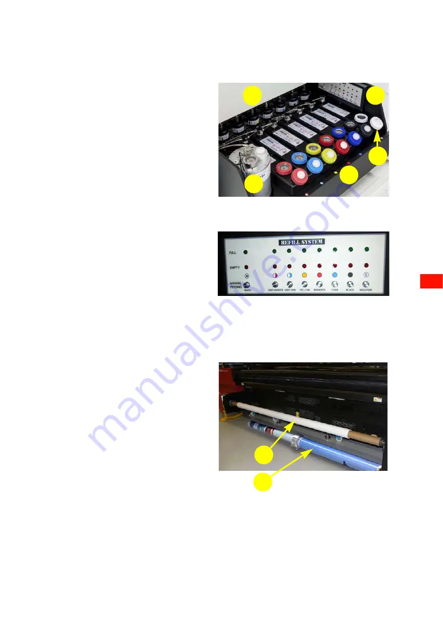
Ink supply drawer

3.1.3

Powered winding axle

The ink supply drawer is located on the right side of 
the printer.
The ink supply drawer consists of:

1 White  container.
2 Six color containers.

- Light magenta
- Light cyan
- Yellow
- Magenta
- Cyan
- Black

3 Solution container.

Note: The term “Solution” is a traditional word 
for what is now called “Storage Flush” and 
some labels on the machine still use the short 
form “Sol”

4 Eight ink filters (one per container).

The function of the ink filter is to keep inpuri-
ties (are larger particles), that could have 
entered the main ink tank, away from the print 
nozzles.

5 Ink refill panel.

The indication light shows when a container 
needs filling. 
• Green is lit: container full.
• Red is lit: container empty and must be 

topped up with 1 liter. 

• Manual  feeding:  Button to pump ink manu-

ally to the sub ink tanks.

1

2

4

5

3

The roll axle [1] at the front of the printer is powered 
by a motor. The powered winding axle winds the 
media and keeps the media under tension. The direc-
tion of rotation of the powered axle can be changed so 
that the roll can be winded up with the print on the 
inside or on the outside.
The media roll is clamped to the axle by bellows, 
which move out of the axle when compressed air is 
supplied to the nozzle of the axle.
The :Anapurna H3200i LED can also handle a dual 
winding axle [2]. The dual winding axle has a clutch 
and flanges to limit the media roll in a lateral direc-
tion on the axle. The clutch and flanges need to be re-
adjusted for different widths of media rolls.
The powered winding axle is an aluminum axle that 
can carry a media roll with weight up to 300 gram per 
centimeter media width (96 kg in case media of 
3200mm width is loaded).

1

2

Содержание Anapurna H3200i LED

Страница 1: ...Anapurna H3200i LED Advanced Operator Manual v1 0 ...

Страница 2: ...tact your local sales representa tive for availability information Agfa Graphics N V diligently strives to provide as accurate information as possible but shall not be respon sible for any typographical error Agfa Graphics N V shall under no circumstances be liable for any damage arising from the use or inability to use any information apparatus method or process disclosed in this document Agfa Gr...

Страница 3: ...l Agfa contact see page 9 Responsibility Symbols and warnings used in this manual The following symbols and warnings are used in this manual Remark The images and description of the User Interface and its operations in this document may not match on printers that were manufactured after the time of its writing Please contact your local Agfa Representative for a copy of the most recent documentatio...

Страница 4: ...www agfagraphics com 4 ...

Страница 5: ... 2 Safety 15 General safety regulations 15 Safety devices 16 Safety sensors light curtains 16 Wing Sensors 16 Safety stop 16 Emergency stop 17 Emergency stop switches 17 Unexpected printer stop 17 Malfunction of the compressed air system 17 Outage electrical power supply 17 Special points of danger 18 Ultraviolet Light 18 Ultraviolet responsive inks 18 Material Safety Data Sheets MSDS 18 Warning s...

Страница 6: ... and settings 37 Options 38 Margins 39 Chapter 5 Startup and Shutdown procedures 41 Differences between shutdown periods 41 Sleep mode 41 Daily 41 Weekend short term shutdown less than 60 hours 41 Holiday long term shutdown longer than 60 hours 41 Procedure sleep mode 42 Procedure daily shutdown 43 Procedure daily startup 44 Procedure weekend shutdown Short Term 45 Procedure Startup after weekend ...

Страница 7: ...roduction Quality 76 Express Quality 76 Draft 76 Calibration 77 Ink dot placement 77 Calibration 77 Calibration zone 78 Horizontal Calibration 78 Bidirectional Calibration 81 Feed calibration 84 White ink circuit 87 Automatic filling of the white ink circuit with storage flush or ink 87 Improved auditive alarm indication 88 Improved visual alarm indication 89 Alarm warning 90 Activate the alarm re...

Страница 8: ...ining the air pressure circuit 110 Replacement 111 Replacing the air filters for the LED modules 111 Replacing the Home Tray filter 1 111 Replacing the air filters for the filler caps of the color tanks 112 Replacing the Home Tray filter 2 Fan Protection filter 112 Chapter 11 Trouble shooting 113 Image Quality Issues 113 iGUI Error Messages 114 Chapter 12 Varia 115 Changing the PID Settings 115 De...

Страница 9: ...nd interior decor become possible and affordable The key mechanical features that enable this versatility are A versatile hybrid media transport that can handle wide media with high precision Versatile control over the ink curing process to optimize color and finish Print head height adjustment with a maximum media thickness of 45 mm Predefined color configurations that meet the ISO 12647 2 standa...

Страница 10: ...tar 400V 10 50 Hz 21A 3 x 30A USA 3 phase no neutral with ground 230V 10 60 Hz 24A 3 x 30A System Integration RIP Integrated production solution with Asanti other RIPs on request Ready to use Anapurna H3200i LED media ink profiles available Asanti Quality Mode Printing speed Ink consumption up to m2 h up to ft2 h Normal ink coverage ml m2 Blue solid ink coverage ml m2 Draft Draft 4C 129 129 1389 1...

Страница 11: ... m2 9 m2 h 75 post white standard opacity 28 ml m2 50 diffusion layer white 18 ml m2 HQ W3 720 x 1440 Uni Quality Fine Mask 100 pre white full opacity 37 ml m2 5 m2 h 75 post white standard opacity 28 ml m2 50 diffusion layer white 18 ml m2 Specification Print heads 6 Konica Minolta KM1024i heads 1024 nozzles head with a droplet vol ume of 12pl colors 2 Konica Minolta KM1024i heads 30pl white in l...

Страница 12: ...hickness Between 0 3 mm and 45 mm Maximum roll weight including aluminum shaft 100 kg 150kg based on 320 cm print width or 31 25 kg m Maximum roll diameter 36 cm 14 17 Core diameter 3 Shafts Steel shaft at input side Aluminum shaft at output side Specification Maximum width Media size 320 cm 126 Printable size 320 cm 126 316 cm 124 with borderless printing Maximum length Supported by 1 rigid rolle...

Страница 13: ... to the printer without prior notification 1 5 Transport re placement installation and commissioning Transport re placement installation and commissioning may only be done by your local Agfa representative For that reason these activities are not written in this manual Please contact your local Agfa representative for these activities Option ABC Code Dual Roll kit OW3E6 Media lifter O9W1N A type p...

Страница 14: ...www agfagraphics com 14 ...

Страница 15: ...heck the presence state and function of the safety devices every day Make sure you know where the emergency switches are located and check to make sure they work cor rectly every day The electrical box may only be opened by qualified personnel and must be closed while the machine is in operation Do not leave the machine unattended while it is in use Wear the specified personal protective equipment...

Страница 16: ...for 60 hours The stirrer of the white ink tank will stop as the electrical switch is NOT driven by the battery backup An empty battery takes 5 days to completely charge again Vertical safety light curtains are installed at the front and back of the printer A safety light curtain consists of two opto electronic beams with a sensing field curtain in between The light curtains are used to detect the ...

Страница 17: ...o the normal start procedure The Inkjet Printer is equipped with emergency stop switches on the front and back of the machine An emergency stop switch is easily recognizable by its red color on yellow background The complete printer stops immediately as soon as one of the E stop switches is pressed power supply and compressed air system are disabled The pressed switch stays mechanically locked and...

Страница 18: ... coat with long sleeves to the wrists to protect against contact burns Warning When performing maintenance tasks that involve UV inks take care to wear an outer garment with sleeves to the wrists nitrile gloves with a thickness of at least 0 2 mm and safety glasses to prevent skin or eye contact Agfa UV inks will penetrate even nitrile gloves in approximately 10 min When there is contact with UV i...

Страница 19: ... the correct personal protective equip ment For work on certain parts of the printer for example UV inks and UV LED units wearing PPE is recom mended Read this manual to find out where PPE is necessary WARNING Moving parts can crush and cut Keep guards in place Keep hands clear Switch Off power before ser vicing WARNING UV Light Do NOT look directly at the light beam Wear protective glasses Contin...

Страница 20: ... machine 2 10 1 Lockout tagout procedure 2 10 2 Removing the padlock Warning When multiple people work on the printer each person must attach his own padlock 1 Shut down the printer refer to chapter 5 2 Turn the Main power switch off 3 Lock the Main power switch with a padlock Warning Once the work has been completed everybody who has fitted a padlock must remove it themselves It is not permitted ...

Страница 21: ...le in Home position 3 1 1 4 Vacuum control panel 4 3 5 Ink supply drawer on right side of printer 3 1 2 6 iGUI operator panel touch screen 4 4 7 Optical safety sensors light curtain 2 2 1 8 Powered take up axle for roll media 3 1 3 9 Vacuum media transport belt 3 1 4 10 Front media set bar 3 1 5 11 Roll to roll media controller 6 5 12 Cutting slit 3 1 6 7 9 10 3 4 7 6 8 2 11 5 1 12 ...

Страница 22: ...te circuits print heads 4 6 color circuits print heads The print area of the print heads is shown by two white arrows on cover 10 of the shuttle 5 UV LED units for curing the ink 6 Ink flow valves 7 Sub air tanks at back of shuttle If the vacuum system has sucked the ink too far it will be collected in two tanks 1 color 1 white with level control 8 Drain valves Each color ink circuit has a drain v...

Страница 23: ...ner empty and must be topped up with 1 liter Manual feeding Button to pump ink manu ally to the sub ink tanks 1 2 4 5 3 The roll axle 1 at the front of the printer is powered by a motor The powered winding axle winds the media and keeps the media under tension The direc tion of rotation of the powered axle can be changed so that the roll can be winded up with the print on the inside or on the outs...

Страница 24: ... as shown by the yellow arrows on the shuttle beam The vacuum is switched ON or OFF by turning the green switch Vacuum on the front panel For more information see chapter 6 The bar is used to align the position of sheet media on the media transport belt relative to the shuttle print heads The bar can be lowered or lifted by turning the red switch Media set on the front panel At the front and back ...

Страница 25: ...uttle in Home position 3 1 1 3 Vacuum unit on left side of printer 3 2 1 4 Optical safety sensors light curtain 2 2 1 5 Back control panel 5 2 6 Transport vacuum controls 3 2 2 7 Vacuum media transport belt 3 1 4 8 Media tension roll 3 2 3 9 Unwinding axle for roll media 3 2 4 10 Cutting slit 3 1 6 4 7 4 1 6 9 10 5 2 3 8 ...

Страница 26: ... the unwinding axle 2 at the back of the printer The unwinding axle has a motor to keep the media under tension The rotational direction of the unwinding motor is opposite to the direction of rotation of the winding motor The rota tion power of the motors is controlled via controllers The media roll is clamped to the axle by bellows which move out of the axle when compressed air is supplied to the...

Страница 27: ...he printer The white lamp is lit when the printer is on 8 PC ON OFF The printer can be operated via the iGUI touch screen panel Press the blue button on the front of the operator panel to start the PC of the printer The blue lamp is lit when the PC is on 9 White Sub Ink Temp PID shows the temperature of the white ink tank red digits processing value indicator actual measured value green digits set...

Страница 28: ...tch the complete printer OFF in case of an emergency 4 Print side IN OFF OUT Switch to change the wind up direction of the take up axle IN media is winded up with the print on the inside OFF the take up axle is switched off OUT media is winded up with the print on the outside 5 Media tension Switch to set the tension of the media roll 6 Media set Switch to send the media set bar UP or DOWN 7 Vacuu...

Страница 29: ...Switch up vacuum ON Switch down vacuum OFF 3 Vacuum color Color ink vacuum pressure controller see 4 3 1 4 Vacuum white White ink vacuum pressure controller see 4 3 1 5 Vacuum white Switch to turn the vacuum for white On or OFF Switch up vacuum ON Switch down vacuum OFF 6 Purge solution Purge solution through the print heads 7 Flow control storage flush Valve to control the flow of storage flush 8...

Страница 30: ...OSE delivery of storage flush closed Vertically down SOL delivery of storage flush opened Each color ink circuit has a valve yellow label to control the flow of ink or storage flush to the print head Position lever Vertically up CLOSE delivery of ink or storage flush closed Horizontally middle INK delivery of ink opened Vertically down SOL delivery of storage flush opened to clear a blocked print ...

Страница 31: ... or OFF 1 Press the green red button 2 A message box pops up eg Turn OFF LM pump 3 Press Yes or No Main ink tank When a main ink tank is almost empty a red letter E appears in the button above the level indicator Sufficient ink is available to finish the print job Sub ink tank When a sub ink tank is almost empty the capital letter in the green button changes into a small letter e g m of magenta Sh...

Страница 32: ... operator to adjust the settings in the relevant calibration tables Each button opens a pop up from which the calibration patterns may be printed and from which the calibration table may be opened to adjust the timing parameters Chapter 7 4 Alignment Parameters Controls the position of the test prints using the left and top margin the speed of the shuttle Carriage Speed and the use of the UV LED u...

Страница 33: ...e printer This button allows the operator to manually move the media over a specific dis tance This button switches the brake ON or OFF This button switches the media tension ON or OFF This button opens the Language selector pop up The pop up shows the current language How to change the current language 1 Select a language 2 Press OK to set the new selection ...

Страница 34: ...The data in this field are for informational purposes only 5 Job Log View Image preview rotate Depending on the Image Rip for us Asanti it may be that the job preview is shown rotated on the iGUI screen upside down and hard to read By checking the check box Image preview rotate the preview of the image is rotated so that it is clearly readable on the Gui screen RTL Error Check check box to perform...

Страница 35: ... printing No Screen field Refer to 1 Color configurations 4 6 1 2 Print control and settings 4 6 2 3 Image Thumbnail display of what is printed 4 Options 4 6 3 5 Operation Start Starts printing the job Button title changes to Pause during the job to permit head cleaning or media feed adjustments Cancel Cancels printing Only active during a print job Percentage bar Shows the progress of the print j...

Страница 36: ...ead Job List Single list of images to be printed one after another in a single queue Multi Queue Up to three lists of images to be printed with the same resolution masking direction and color configuration in three queues There are a number of combinations that may be selected for exceptional printing situations by clicking the Advanced Configs button Each configuration achieves particular effects...

Страница 37: ...Left and Right UV lamp intensity Min 20 Max 100 UV Controls the UV LED sequence ON OFF RTL Info RTL information field Print Mode Settings for the print quality 4 6 2 1 S ingle Strike D ouble Strike Will print each dot ones Will print each dot twice Mirror Print image mirrored Horizontal Vertical The Quality mode improves the quality by printing in multiple passes to print each layer giving finer c...

Страница 38: ...p and Repeat See description below 0 x Number of vertical copies Return Media This option is used to print multiple layers exactly on top of each other during multiple print runs When check box is checked the media is moved back in Y direction to the start position of the previous print run If you want to use this option you have to check the check box before starting the print job Null Point Retu...

Страница 39: ...mm 40 mm border in the figure shown above Top When you want to start printing on the edge of the media you enter 0 When you want to have a white border add the desired width in mm of the border e g 30 mm in the figure shown above Right The UV LED units may not stop above the media during printing as this may result in distortion of the media In this field enter the distance of the shuttle travel n...

Страница 40: ...more images are printed after each other on roll media When you want to print the images against each other you enter 0 When you want to have a white border between the images add the desired width in mm of the border e g 30 mm in the figure shown above Right The UV LED units may not stop above the media during printing as this may result in distor tion of the media In this field enter the distanc...

Страница 41: ... This situation is termed a long term shutdown 5 7 Procedure Holiday shutdown Long Term 5 8 Procedure Startup after a Long Term Shutdown Remark regarding white ink The white UV ink does not flow as well as the color inks at room temperature and so is more prone to sedimentation in tanks and heads which can cause blockages in tubes White UV ink must be circu lated and stirred to keep its print head...

Страница 42: ...perform some actions to cancel the sleep mode and return to normal use 1 Press OK The message box disappears and the control menu appears 2 Clean the print heads See 7 2 Checking and clearing noz zles 3 Close home tray 4 Wait until Head base temperature on the PID is correct Color sub ink temperature on the PID is correct White sub ink temperature on the PID is correct 5 Startup the production ...

Страница 43: ...f the vacuum of the media transport belt 4 Remove the media used for the prime check 5 Move the shuttle to the home position it lowers itself to its minimum height Normally the shuttle is in the home posi tion 6 Leave the color flow valves 1 in the position ink 7 Leave the storage flush flow valve 2 in the position close 8 Leave the vacuum switches 3 and 4 on 9 On the control screen press button H...

Страница 44: ... sleep mode Perform the procedure Sleep mode see section 5 2 2 Load some media see chapter 6 3 Perform the procedure to set the media thickness see 7 1 Setting Head Gap 4 Perform a prime check and clean the print heads if needed see 7 2 Checking and clearing nozzles 1 7 8 3 9 11 12 2 4 5 6 10 ...

Страница 45: ... off the vacuum of the media transport belt 4 Remove the media used for the prime check 5 Move the shuttle to the home position it lowers itself to its minimum height Normally the shuttle is in the home posi tion 6 Switch the color flow valves 1 in the position close 7 Leave the storage flush flow valve 2 in the position close 8 Switch the color vacuum switch 3 off 9 Leave the white vacuum switch ...

Страница 46: ...tor lamp 12 is lit 3 Start the iGUI program 4 Switch the color vacuum switch 13 on 5 Switch the color flow valves 14 in the position ink 6 Load some media see chapter 6 7 Perform the procedure to set the media thickness see 7 1 Setting Head Gap 8 Perform a prime check and clean the print heads if needed see 7 2 Checking and clearing nozzles 14 13 1 7 8 3 9 11 12 2 4 5 6 10 ...

Страница 47: ...e fixed in place during the down time This is why the procedures start with a prime check 8 On the iGUI turn off the delivery pumps for white ink and storage flush see also section 4 4 2 1 9 Switch off the white ink vacuum 1 10 Press and hold the purge button 2 for 3 seconds Storage flush flows out of the white head 11 Repeat step 10 approx 20x till no more storage flush is flowing out of the whit...

Страница 48: ...lor ink circuits 14 12 Switch all color flow valves 15 yellow labels to ink position White circuit 13 Switch ON the vacuum for the white ink circuit 16 14 On the iGUI turn on the delivery pumps for white ink and storage flush see also section 4 4 2 1 15 On the control screen press button Home Cover to open the home cover 16 Fill the white ink circuit with ink follow the proce dure of section 7 6 1...

Страница 49: ...uum compartments 4 sets of valves and gauges Media transport belt Vacuum unit to provide the vacuum pressure Vacuum system controller called an inverter Motor driven unwinder and rewinder system 6 2 Vacuum Pressure Settings Transport vacuum valves When a compartment is not fully covered the uncovered area lets air flow around the media reducing the effect of the vac uum Depending on the size and o...

Страница 50: ...esults over the complete media surface The media must be fully supported by the media table so they can not deform Example of the small media feed tables front and back Example of a large extension media table Large extension tables For a media depth greater than 1m and up to 3 2 m the large extension tables are needed Spirit levels Before using the media tables check that all the spirit levels ar...

Отзывы: