advanced FLOW engineering
Instruction Manual
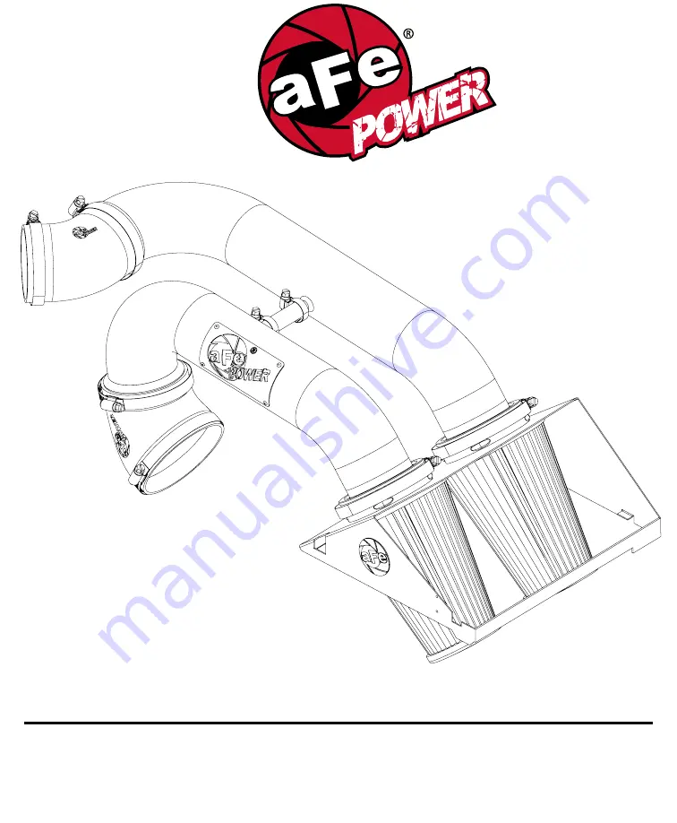
P/N: 51-22642-B / 54-22642-B
Make:
Ford
Model:
F-150
Year:
2015-2021
Engine:
V6-2.7L (tt) EcoBoost
2015-2016
V6-3.5L (tt) EcoBoost
Страница 1: ...advanced FLOW engineering Instruction Manual P N 51 22642 B 54 22642 B Make Ford Model F 150 Year 2015 2021 Engine V6 2 7L tt EcoBoost Make Ford Model F 150 Year 2015 2016 Engine V6 3 5L tt EcoBoost ...
Страница 2: ...s 8mm Nut Driver Flat Head Screwdriver Note Legal in California for use on race vehicles only The use of this device on vehicles used on public streets or highways is strictly prohibited in California and others states that have adopted California emission regulations Please read the entire instruction manual before proceeding Ensure all components listed are present If you are missing any of the ...
Страница 3: ...aFepower com Page 3 B1 A1 A2 B2 C D E K F F F G G H I J ...
Страница 4: ...e 1 Step 2 Loosen the OE intake clamps using an 8mm nut driver from the left and right side runners 2 Step 3 Unclamp the top portion of the OE airbox 3 Step 4 Remove the OE intake and the top portion of the OE airbox by pulling straight up and out of the vehicle REMOVAL Page 4 Figure A 2 2 3 1 ...
Страница 5: ...Refer to Figure B for Step 5 Step 5 Install trim seal onto the air filter housing Page 5 aFepower com INSTALL Figure B ...
Страница 6: ... from the OE intake turn counter clockwise Step 7 Install the sensor into the rear aFe intake tube Step 8 Install housing and retain with the factory clips Step 9 Install filters from inside the housing Make sure they are inserted flush and filter retention bumps hold them in place ...
Страница 7: ... Install the small 5 8 x 3 hose on the crossover tube with the appropriate clamps but do not tighten Step 11 Fit tubes into the remaining couplers Adjust for best fit and tighten all clamps Step 12 Connect sensor harness to the Temp Sensor Page 7 aFepower com ...
Страница 8: ...nstalled on the engine It is shown off the vehicle for better illustration Step 13 Locate the o e plastic tube feeding the driver s side turbo inlet Refer to Figure E for Step 13 For V6 3 5L tt only not necessary on V6 2 7L tt Figure E INSTALL Vent insert installation ...
Страница 9: ...efer to Figure F for Step 14 For V6 3 5L tt only not necessary on V6 2 7L tt Step 14 Locate the valve cover vent tube that feeds into driver s side turbo inlet It is not necessary to remove the engine cover Figure F INSTALL ...
Страница 10: ...d tail and pull vent fitting off of the turbo inlet tube It is not necessary to disconnect at the valve cover end There is a sensor and wire harness on this vent tube Do not damage or remove these components Refer to Figure G for Step 15 For V6 3 5L tt only not necessary on V6 2 7L tt Figure G INSTALL ...
Страница 11: ...ure H for Step 16 For V6 3 5L tt only not necessary on V6 2 7L tt Step 16 Insert vent fitting with slash cut facing turbo inlet It should not be a loose fit It is direction dependent and must not rotate once installed INSTALL Figure H ...
Страница 12: ...Installation is complete Any codes can be cleared with a code reader or by disconnecting the battery You will lose any radio presets with battery disconnection NOTE If removal of the vent insert is required it can be pulled out with internal snap ring pliers Refer to Figure I for Steps 17 18 For V6 3 5L tt only not necessary on V6 2 7L tt Figure I INSTALL ...
Страница 13: ...r com Page 13 5 Step 19 Make sure all clamps and screws are tight Your installation is now complete NOTE Check all bolts clamps and connectors after 100 200 miles Refer to Figure J for Step 19 Figure J INSTALL ...
Страница 14: ...Page 14 PAGE LEFT BLANK INTENTIONALLY ...
Страница 15: ...aFepower com Page 15 PAGE LEFT BLANK INTENTIONALLY ...
Страница 16: ...advanced FLOW engineering inc 252 Granite Street Corona CA 92879 TEL 951 493 7100 TECH 951 493 7134 E Mail Tech aFepower com P N 06 81072 ...