Installation, assembly and setting
Assembly instructions EN
DG 16
Edition 07/2020
Rev. 3.0
37–50
6.4.2 Adjustment of the rotary gripper modules DG 16
The rotary grippers are equipped with several compressed-air connections air
to meet the various requirements.
The various settings and connections are listed below.
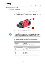
Black part of the rotary gripper module (Fig. 19, 1): Connections for the
gripping movement.
Red part or the rotary gripper module (Fig. 19, 2): Connections for the
rotation of the gripping jaws.
The end positions can be set to +/-5°.
For positioning insert the supplied centering sleeves into the mounting holes
of the mounting grid.
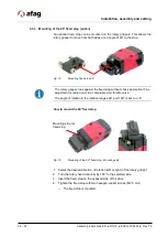
Fig. 19
Example rotary gripper DG 16
We recommend using pneumatic compressed air valves so that the control of
the rotary grippers can be better regulated.
2
1

