background image


Safety instructions


10 – 50 

Assembly instructions EN  


DG 16  


Edition 07/2020  

  Rev. 3.0


2  Safety instructions 

2.1  General 

This chapter provides an overview of important safety aspects to ensure safe 

and proper use of the rotary gripper and optimal protection of personnel. 


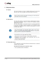
Failure to follow the directions and safety instructions given in this instructions 

manual may result in serious hazards. 

2.2  Intended use 

The DG 16 rotary grippers are used for shock-free gripping/rotating of loads in 

non-hazardous atmospheres under the ambient and operating conditions 

defined for these modules. 
The DG 16 rotary grippers are designed exclusively for gripping payloads that 

do not pose any danger to persons, property or the environment during 

manipulation. In combination with other modules the rotary grippers can be used 

as a pick & place Station. 


In the chemical industry and in potentially explosive areas, the use of rotary 

grippers is not permitted without additional safety measures. In such cases, 

please consult with the Afag technical department. 


The intended use of the rotary gripper also includes: 

 Observance of all instructions given in these assembly instructions. 

 Compliance with the inspection and maintenance work and the 

specifications in the data sheets. 

 Using only original spare parts. 

2.3  Foreseeable misuse 

Any use other than or beyond the intended use described above is considered 

a misuse of the rotary gripper. 

Especially the following use is considered a misuse: 

  Use in potentially explosive atmospheres 


Содержание DG 16

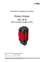
Страница 1: ...N DG 16 Edition 07 2020 Rev 3 0 1 50 Assembly Operating Instructions Rotary Gripper DG 16 DG 16 zero position 90 Translation of the Original Assembly Instructions EN DG 16 Order no 50294010 DG 16 zero pos 90 Order no 50407663 ...

Страница 2: ...am Subject to modifications The rotary grippers have been designed by Afag Automation AG according to the state of the art Due to the constant technical development and improvement of our products we reserve the right to make technical changes at any time Copyright 2020 Afag Automation AG All contents of the present assembly and operating instructions in particular the texts photographs and graphi...

Страница 3: ...nnel qualification 12 2 6 Personal protective equipment PPE 13 2 7 Changes and modifications 14 2 8 General hazards Residual risks 14 2 8 1 General hazards at the workplace 14 2 8 2 Danger due to electricity 15 2 8 3 Mechanical hazards 16 2 8 4 Danger due to pneumatics 16 2 8 5 Danger caused by omitting maintenance work 16 3 Technical data 17 3 1 Dimensional drawing DG 16 17 3 2 Technical data DG ...

Страница 4: ...6 3 4 Mounting of the 90 fixed stop option 34 6 3 5 Assembly of the sensors 35 6 4 Settings 36 6 4 1 Safety instructions for adjustment work 36 6 4 2 Adjustment of the rotary gripper modules DG 16 37 7 Commissioning 38 7 1 Safety instructions for commissioning 38 7 2 Commissioning of the rotary grippers 38 8 Fault elimination 39 8 1 General notes 39 8 2 Safety instructions for troubleshooting 39 8...

Страница 5: ...Table of contents Assembly instructions EN DG 16 Edition 07 2020 Rev 3 0 5 50 10 2 Decommissioning 45 10 3 Disassembly 45 10 4 Disposal 46 11 Declaration of incorporation 47 ...

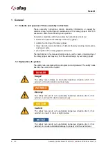
Страница 6: ...ions in this manual shall provide you with a basic understanding of the rotary gripper and may vary from the actual design of your rotary gripper 1 2 Explanation of symbols The safety notes are marked by a pictogram and a signal word The safety notes describe the extent of the hazard DANGER Danger This safety note indicates an imminently hazardous situation which if not avoided will result in deat...

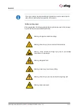
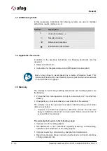
Страница 7: ...icable the following standardised symbols are used in this manual to point out the various potential health risks Warning Dangerous electrical voltage Warning Risk of injury from contact with hot surfaces Warning Risk of hand and finger injury due to uncontrolled movements of components Warning Magnetic field Warning back injury due to heavy lifting Warning Risk of injury as a result of parts bein...

Страница 8: ...gripper 1 5 Warranty The warranty terms for Afag handling components and handling systems are the following 24 months from initial operation and up to a maximum of 27 months from delivery Wear parts e g shock absorbers are excluded from the warranty The warranty covers the replacement or repair of defective Afag parts Further claims are excluded However a customer has a right to a defect free prod...

Страница 9: ...Machinery Directive the Accident Prevention Regulations the Standards of the German Electrotechnology Association VDE and these safety and assembly instructions 1 6 Liability No changes shall be made to the rotary grippers DG 16 unless described in this manual or approved in writing by Afag Automation AG Afag Automation AG accepts no liability for unauthorized changes or improper assembly installa...

Страница 10: ...s that do not pose any danger to persons property or the environment during manipulation In combination with other modules the rotary grippers can be used as a pick place Station In the chemical industry and in potentially explosive areas the use of rotary grippers is not permitted without additional safety measures In such cases please consult with the Afag technical department The intended use o...

Страница 11: ...y professional qualifications and experience are familiar with the basic rules regarding occupational safety and accident prevention have been instructed in the correct handling of the rotary grippers have read and understood these assembly instructions The operating company is also required to Monitor on an ongoing basis that the personnel work safely considering any potential hazard involved and...

Страница 12: ...may be permitted to carry out the described activities on the rotary grippers Persons whose ability to react is restricted due to the intake of medication or the like must not interact with the rotary grippers These installation instructions are intended for skilled personnel installers system integrators maintenance personnel technicians electricians and operating personnel The following is a des...

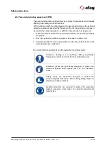
Страница 13: ...oyer check the personal protective equipment for proper condition and immediately notify the person responsible on site of any defects found on the personal protective equipment Personal protective equipment and the respective mandatory signs Protective clothing is a close fitting clothing specifically designed to protect personnel from hazards during work Protective gloves are specifically design...

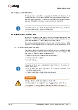
Страница 14: ...operating the rotary grippers Observe the safety instructions in this chapter and in the other sections of this manual to avoid damage to material and dangerous situations for the personnel 2 8 1 General hazards at the workplace The machine has been built according to the state of the art and the applicable health and safety requirements However improper use of the rotary grippers may cause the fo...

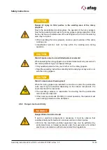
Страница 15: ...mage Only qualified personnel may work with or on the rotary grippers Read the assembly instructions carefully before carrying out any work on or with the rotary grippers CAUTION Risk of noise induced hearing loss When the rotary grippers are installed in a machine or plant the permissible noise level may be exceeded depending on the various components the environment and the resonance The operati...

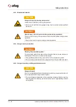
Страница 16: ... system during normal operation Never reach into the system during normal operation WARNING Risks by the pneumatic system The pneumatic system can pose various hazards that can cause serious or fatal injuries if the work is carried out improperly Only qualified personnel may work with or on the pneumatic system The necessary personal protective equipment must be provided and used CAUTION Danger of...

Страница 17: ...Technical data Assembly instructions EN DG 16 Edition 07 2020 Rev 3 0 17 50 3 Technical data 3 1 Dimensional drawing DG 16 Fig 1 Dimensional Drawing Rotary Gripper DG 16 ...

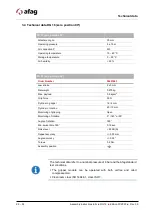
Страница 18: ...kg Max payload 0 5 kgcm2 Grip force 35 N Cylinder gripper 16 4 mm Cylinder rotation 20 10 mm Monitoring of gripping Open Monitoring of rotation 0 180 or 90 Angle of rotation 180 Min swivel time 180 0 19 sec Noise level 65 dB A Repeat accuracy 0 03 mm Angle accuracy 0 05 Torque 0 4 Nm Assembly position The technical data refer to a nominal pressure of 6 bar and the Afag standard test conditions The...

Страница 19: ...Technical data Assembly instructions EN DG 16 Edition 07 2020 Rev 3 0 19 50 3 3 Dimensional drawing DG 16 zero position 90 Fig 2 Dimensional Drawing Rotary Gripper DG 16 zero position 90 ...

Страница 20: ...2 x 3 mm Net weight 0 275 kg Max payload 0 5 kgcm2 Grip force 35 N Cylinder gripper 16 4 mm Cylinder rotation 20 10 mm Monitoring of gripping Open Monitoring of rotation 0 180 or 90 Angle of rotation 180 Min swivel time 180 0 19 sec Noise level 65 dB A Repeat accuracy 0 03 mm Angle accuracy 0 05 Torque 0 4 Nm Assembly position The technical data refer to a nominal pressure of 6 bar and the Afag st...

Страница 21: ...instructions EN DG 16 Edition 07 2020 Rev 3 0 21 50 3 5 Preferred combinations DG 16 3 6 Rotation time diagram DG 16 Rotation time diagram Fig 3 Rotation time diagram DG 16 Rotation time s Rotation time Mass moment of inertia ...

Страница 22: ...G 16 Centric gripping force diagram closing opening Fig 4 Centric gripping force diagram DG 16 3 8 Load of gripper fingers DG 16 Fig 5 Load of gripper fingers DG 16 Type DG 16 Max static torque Mx 3Nm Max static torque My 3 Nm Max static torque Mz 10 Nm Max static force Fz 50 N Centric gripping force closing time ...

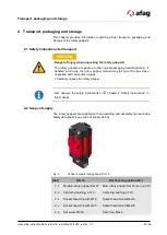
Страница 23: ...safety data sheet see scope of supply below Fig 6 Scope of supply rotary gripper DG 16 Unt DG 16 DG 16 zero position 90 1 x Module rotary gripper DG 16 Mod rotary gripper DG 16 zero p 90 2 x Centering bushing ø 7x3 Centering bushing ø 7x3 2 x Socket head screw M4x16 Socket head screw M4x16 2 x Socket head screw M4x35 Socket head screw M4x35 2 x Set screw M3x3 Set screw M3x3 CAUTION Danger of injur...

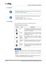
Страница 24: ...rds top side of the package Fragile Products marked with this symbol shall be handled with care and may never be turned upside down or tied up Protect against moisture The packages shall be protected against moisture and kept dry keep covered during storage Attachment points The hosting equipment chain etc may only be attached to the points marked by this symbol Centre of gravity This symbol marks...

Страница 25: ...ve the following Do not store the rotary grippers outdoors or expose them to weather conditions The storage space must be dry and dust free Room temperature of the storage space 0 50 C Relative air humidity 90 non condensing Clean the rotary grippers and protect the blank metal parts against corrosion using the appropriate means Protect the rotary grippers from dirt and dust ...

Страница 26: ...G 16 series are precision devices In order ensure safe and reliable operation it is important that the rotary gripper modules are handled with care The DG 16 modules are highly compact pneumatic rotary grippers and can be used for gripping turning and swivelling small mass produced parts The rotary grippers are equipped with a parallel gripper head and can be mounted either vertically or horizonta...

Страница 27: ...6 DG 16 zero position 90 End stop 90 DG 16 End stop 90 DG 16 zero position 90 Order Number 50307648 Order Number 50525638 Net weight 0 007 kg Net weight 0 01 kg Fig 8 End stop 90 DG 16 end stop 90 DG 16 zero position 90 Attachment kit sensor holder 90 DG 16 Order Number 50435052 Net weight 0 275 kg Fig 9 Attachment kit sensor holder 90 DG 16 ...

Страница 28: ...r Number 50313987 Net weight 0 021 kg Operating voltage 10 30 VDC Proximity switch INI c10x9 Em PNP NO M8x1 Order Number 50313986 Net weight 0 02 kg Operating voltage 10 30 VDC 5 3 3 Connections DG 16 Proximity switch cable R10 0 1 m 0 00 Order Number 50386489 Net weight 0 001 kg Compressed air connection straight M3x0 5 Order Number 50073314 Net weight 0 001 kg ...

Страница 29: ...rs on our website www afag com 5 4 Field of application and assembly options 5 4 1 Assembly example DG 16 In combination with other modules the rotary grippers can be used as a pick place Station The following are some examples of possible assembly options Fig 10 Example rotary gripper DG 16 Units Mounting kit Order no 1 x Sensor holder DG 16 50435052 2 x Hexagon socket head screw M4x14 DIN 912 2 ...

Страница 30: ...ed personnel Read carefully the assembly and safety instructions before working with or on the rotary grippers CAUTION Danger of injury when handling the rotary grippers Careless handling of the rotary grippers can cause personal injuries and damage to the rotary grippers Only qualified personnel may work with or on the rotary grippers Observe the assembly instructions NOTICE No liability for dama...

Страница 31: ...the gripping jaw or the rotary head Fig 11 Example rotary gripper DG 16 The maximum length of the gripper fingers is 30 mm Observe the maximum permissible gripper finger loads in Chapter 3 1 6 Technical Data in this manual Attachment to the rotary head Fig 12 Example rotary gripper DG 16 For the 90 end stop fixed stop of the DG 16 the customer can mount his own components such as hold down devices...

Страница 32: ...2 centering sleeves Ø 7x3 mm Fig 13 Rotary gripper Centering of the module The rotary grippers can be mounted both in horizontal and vertical position The dimensions of the mounting holes and the distances between holes are indicated in the dimensional drawings in Chapter 3 Technical Data 6 3 2 Tightening torques for screws For assembling use screws with the following minimum specifications Standa...

Страница 33: ...we recommend setting the signal Part gripped at half the jaw stroke length The full jaw stroke length should not be limited Example DG 16 Jaw stroke 2x3 mm Part gripped at 2x1 5 mm Operating pressure 6 bar 1 bar The minimum compressed air quality shall comply with the specifications of ISO 8573 1 2010 NOTICE Functional impairment to leaking compressed air connections Unused air connections that ar...

Страница 34: ...op without shock absorption Fine adjustment is carried out via a compressed air throttle valve The angle of rotation in the rotation ranges 90 and 180 is set to 5 How to mount the 90 fixed stop Fig 16 Mounting of the 90 fixed stop Mounting side 1 Select the desired direction of rotation left or right of the rotary gripper 2 Turn the rotary head manually by 180 to the selected side 3 Insert the fix...

Страница 35: ...s integrated in the C slots These accessories are listed in chapter 5 3 Fig 17 DG proximity switches X Magnetic cylinder sensor for easy teaching of 2 monitoring positions The sensors must be adjusted to the end positions of the rotary grippers Positioning Teachable sensors When setting teachable sensors pay attention to the markings on the rotary gripper module Fig 18 Display of teachable sensors...

Страница 36: ...of the system equipment Uncontrolled movements of parts can cause injury to third parties and damage to property Ensure that there are no persons in the working area of the rotary grippers CAUTION Danger of injury from uncontrolled restarting of the system equipment Unintentional restarting of the controller or the pneumatic system can cause injuries and material damage When working on the rotary ...

Страница 37: ...ns are listed below Black part of the rotary gripper module Fig 19 1 Connections for the gripping movement Red part or the rotary gripper module Fig 19 2 Connections for the rotation of the gripping jaws The end positions can be set to 5 For positioning insert the supplied centering sleeves into the mounting holes of the mounting grid Fig 19 Example rotary gripper DG 16 We recommend using pneumati...

Страница 38: ... no persons or tools in the working area 3 Then perform a test run Start with slow movements Then continue under normal operating conditions Commissioning is completed CAUTION Danger of injury by moving components Limbs can be crushed by moving components Work on and with the rotary grippers may only be carried out by qualified personnel Make sure that there are no persons or tools in the working ...

Страница 39: ...nnected Module defect Reduce payload Increase pressure to max 8 bar Check pneumatic hoses Send module to Afag for overhaul Gripper jaws do not move to end position Payload too high Pressure too low Rotary gripper incorrectly connected Module defect Reduce payload Increase pressure to max 8 bar Check pneumatic hoses Send module to Afag for overhaul Compressed air audibly escapes from the rotary gri...

Страница 40: ...ion the initiator correctly Repeat teaching of the initiator Replace the steel studs at the rear part of the rotary gripper with the M3x5 plastic studs included in the accessories kit and screw them in carefully until stop position Sensor fault in the rear area of the rotary gripper No sensor signal Sensor fault 8 3 2 Insert optional plastic screws 8 3 2 Sensor fault In case of sensor faults you c...

Страница 41: ...er of injury due to improper maintenance Improperly carried out maintenance activities can cause considerable damage to property and serious injury The operator must exercise due care and only use trained maintenance personnel to carry out the activities Always wear personal protective equipment when carrying out maintenance and repair work WARNING Risk of injury due to uncontrolled movements of t...

Страница 42: ... water do not use aggressive cleaning agents Perform a visual inspection of the rotary gripper NOTICE Risk of damage to property Torx type hexagon socket screws may only be loosened by the manufacturer Afag Otherwise the rotary grippers could be damaged Only Inbus type hexagon socket screw may be loosened by the operator NOTICE Risk of corrosion due to ionized air environment If the rotary gripper...

Страница 43: ...quantity 5 10 drops of oil per 1000 ltr Compressed air Viscosity range 9 11 mm2 s cST at 40 C ISO class VG 10 acc ISO 3448 9 3 3 Further maintenance Further maintenance is not required if the ambient conditions listed below are complied with Clean working area No use of splash water No abrasive or process dust and vapours Climate and temperature as specified in the technical data NOTICE Risk of da...

Страница 44: ...e parts for the rotary grippers Please note that Afag does not assume any warranty for rotary grippers that have not been replaced or repaired by Afag CAUTION Risk of injury when removing the rotary grippers due to uncontrolled movements of the grippers When disassembling the rotary grippers from a system there is a danger of uncontrolled movements Disconnect the media supply electrics pneumatics ...

Страница 45: ...10 3 Disassembly The rotary grippers may only be dismounted by qualified personnel WARNING Risk of injury due to improper decommissioning disassembly and disposal Improperly carried out activities can result in considerable material damage and serious injury The operator must exercise due care and only use specially trained and qualified personnel for this work CAUTION Risk of injury due to uncont...

Страница 46: ...ate the various components according to type of material and dispose of them properly Scrap the metallic materials Hand over plastic parts for recycling Sort the rest of the components by their material properties and dispose of them accordingly NOTICE Risk to the environment due to incorrect disposal of the packaging material Environmental damage can be caused by incorrect disposal of the packagi...

Страница 47: ...monised standards applied in particular EN ISO 12100 2010 Safety of machinery General design principles Risk assessment and risk reduction Note The partly completed machinery must not be put into service until the machinery into which it is to be incorporated has been declared in conformity with the provisions of Machinery Directive 2006 42 EC The manufacturer undertakes to transmit in response to...

Страница 48: ...O Obligations and liability 11 Obligations of the operating company 11 Obligations of the personnel 12 Operation 39 Operator 12 P Packaging 24 Personal protective equipment PPE 13 Personnel qualifications 12 Personnel requirements 12 Protective clothing 13 Protective gloves 13 Q Qualified electrician 12 Qualified personnel 12 R Reports certificates plans 8 Residual risks 14 S Safety instructions 1...

Страница 49: ...6 26 Fig 8 End stop 90 DG 16 end stop 90 DG 16 zero position 90 27 Fig 9 Attachment kit sensor holder 90 DG 16 27 Fig 10 Example rotary gripper DG 16 29 Fig 11 Example rotary gripper DG 16 31 Fig 12 Example rotary gripper DG 16 31 Fig 13 Rotary gripper Centering of the module 32 Fig 14 Pneumatic diagram DG 16 33 Fig 15 Mounting fixed stop 90 34 Fig 16 Mounting of the 90 fixed stop Mounting side 34...

Страница 50: ...50 50 Assembly instructions EN DG 16 Edition 07 2020 Rev 3 0 ...

Отзывы: