1.3. Understanding Basic HEX500-350HL Operation
1.3.1. Hexapod Axes
The hexapod platform can be actuated in six degrees of freedom by changing the lengths of the six
struts that connect the platform to the base. Since the axes of motion are not obvious from the
mechanics of the hexapod, the axis convention is outlined below. These axes can be used to orient
the hexapod in the global workspace. Refer to the HexGen
®
Programming Guide for more
information about controlling hexapod motion. To get a copy of this guide, go to the
section of www.aerotech.com. Select the
Manuals and Help Files
tab. Then download
Hexapod
Programming User Guide
from the
User Guides
category.
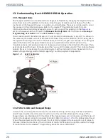
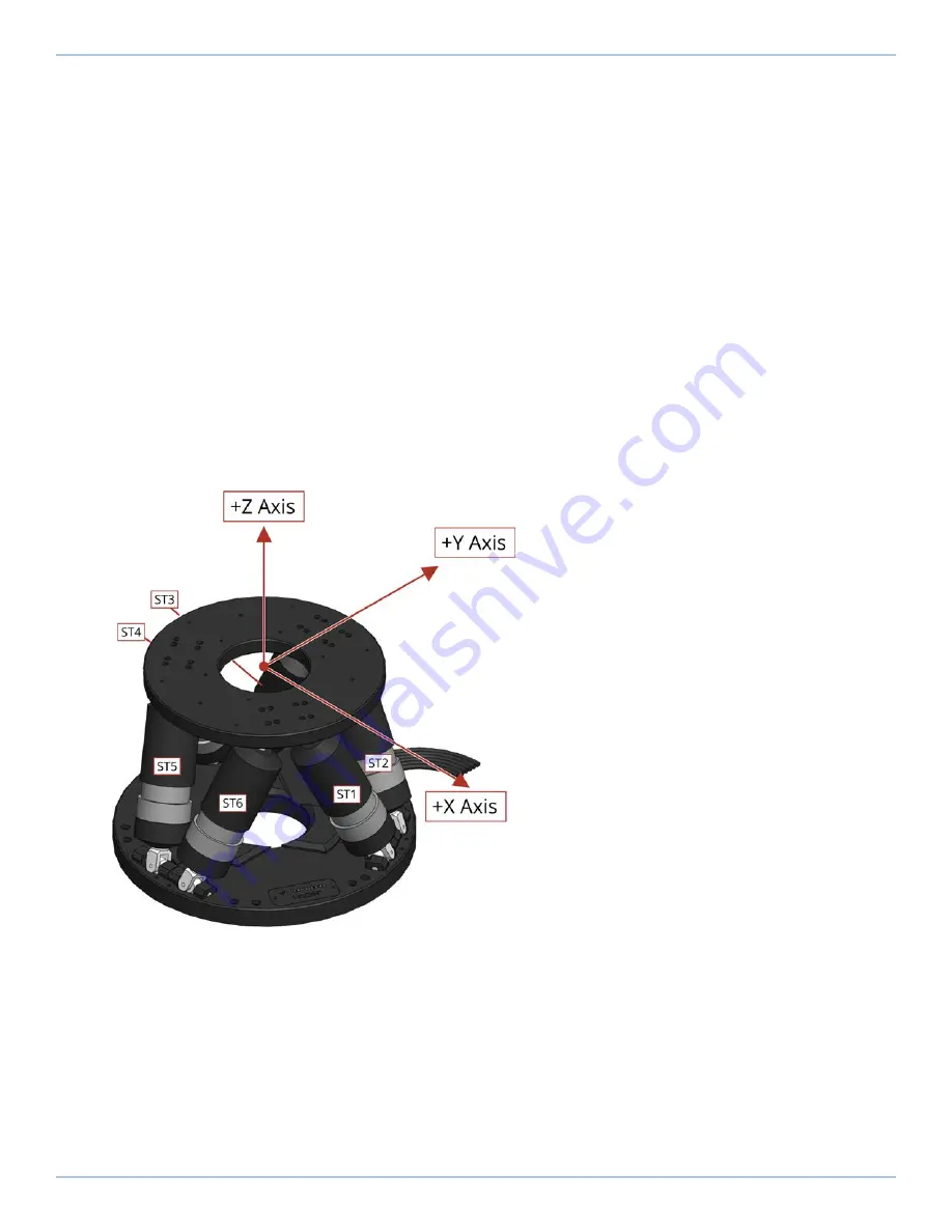
The six axes include 3 translational axes, X, Y, and Z, and 3 rotational axes, A, B, and C. As shown in
the overview, the cables exit out of the back of the base. The positive direction of the X axis goes to
the right when looking at the front of the hexapod, and the Z axis goes up vertically. The Y axis goes
toward the back of the hexapod. Rotational axes are oriented in the same direction as the
translational axes, and positive rotation is clockwise when looking in the direction of the axis. The A
axis rotates about the X axis, B rotates about the Y axis, and C rotates about Z. The control software
enables the user to customize the coordinate system with certain restrictions. Please refer to the
HexGen Programming guide for details regarding coordinate system manipulation.
Figure 1-2:
Axis Orientation
1.3.2. Strut Limits and Hexapod Range
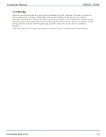
Limits on the strut keep the strut within the useable travel range. When any strut has reached the
end of travel in either direction, an error will occur in the controller. Because the ranges of the
hexapod axes are interdependent, the limits of the hexapod axes are not constant, and the range of
motion of a hexapod cannot be concisely described. Refer to
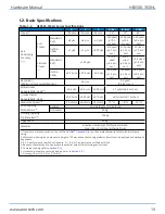
for the independent travel
of each hexapod axis and the strut travel. If a strut limit is triggered, the hexapod is out of range. In
this case, follow the directions of the controller to return the hexapod to a position within the range
of motion. Refer to the HexGen
®
Programming Guide for more information.
HEX500-350HL
Hardware Manual
20
www.aerotech.com
Содержание HexGen HEX500-350HL
Страница 1: ...Revision 2 01 HexGen HEX500 350HL Hexapod Six DOF Positioning System HARDWARE MANUAL...
Страница 16: ...This page intentionally left blank HEX500 350HL Hardware Manual 16 www aerotech com...
Страница 22: ...This page intentionally left blank HEX500 350HL Hardware Manual 22 www aerotech com...
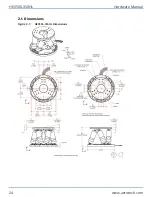
Страница 24: ...2 1 Dimensions Figure 2 1 HEX500 350HL Dimensions HEX500 350HL Hardware Manual 24 www aerotech com...
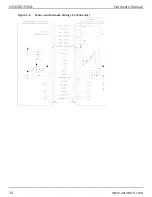
Страница 34: ...Figure 3 2 Motor and Feedback Wiring E3 Connector HEX500 350HL Hardware Manual 34 www aerotech com...
Страница 39: ...Figure 3 5 Encoder Phasing Reference Diagram Standard Hardware Manual HEX500 350HL www aerotech com 39...
Страница 40: ...This page intentionally left blank HEX500 350HL Hardware Manual 40 www aerotech com...
Страница 44: ...This page intentionally left blank HEX500 350HL Hardware Manual 44 www aerotech com...
Страница 48: ...This page intentionally left blank HEX500 350HL Hardware Manual 48 www aerotech com...


