


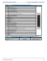
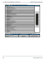


3.1. Motor and Feedback Connectors
DANGER
: To decrease the risk of electrical shock, injury, death, and damage to the
equipment, obey the precautions that follow.
l
Make sure that all components are grounded correctly and that they obey the local
electrical safety requirements.
l
It is the responsibilty of the system integrator or qualified installer to determine and
meet all safety and compliance requirements when they integrate the AGV3D into a
completed system.
l
Restrict access to the AGV3D when it is connected to a power source.
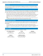
If the AGV3D is built with standard Aerotech motors and encoders, it will arrive from the factory
completely wired and assembled.
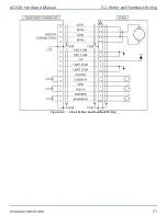
The X- and Y-axis galvo motors produce dual analog encoder feedback signals. The Z-axis motor
produces single analog encoder feedback signals. The Primary (X, Y, and Z) and Secondary (X and Y)
position feedback signals must be tuned for optimal performance. Use the Feedback Tuning Tab of the
Digital Scope utility to adjust the gain, offset, and phase balance of each channel. Refer to the Nmark
GCL or GL4 Controller Hardware Manual and the Help for more information.
Figure 3-1:
Connectors
IMPORTANT
: The protective ground connection of the AGV3D provides motor frame
ground protection only. Additional ground and safety precautions are required for
applications that require access to the AGV3D while it is energized.
3.1. Motor and Feedback Connectors
AGV3D Hardware Manual
46
www.aerotech.com
Содержание AGV3D Series
Страница 1: ...Revision 2 00 AGV3D Three Axis Laser Scan Head HARDWARE MANUAL...
Страница 6: ...This page intentionally left blank List of Tables AGV3D Hardware Manual 6 www aerotech com...
Страница 12: ...This page intentionally left blank Laser Shutter AGV3D Hardware Manual 12 www aerotech com...
Страница 14: ...This page intentionally left blank EU Declaration of Incorporation AGV3D Hardware Manual 14 www aerotech com...
Страница 16: ...Figure 1 2 Standard AGV3D Chapter 1 Overview AGV3D Hardware Manual 16 www aerotech com...
Страница 28: ...This page intentionally left blank 1 4 Software Configuration AGV3D Hardware Manual 28 www aerotech com...
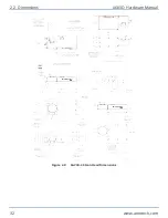
Страница 32: ...Figure 2 2 AGV3D 30 Scan Head Dimensions 2 2 Dimensions AGV3D Hardware Manual 32 www aerotech com...
Страница 60: ...This page intentionally left blank Appendix B Revision History AGV3D Hardware Manual 60 www aerotech com...


