3.4. Limits, Marker, and Machine Direction
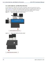
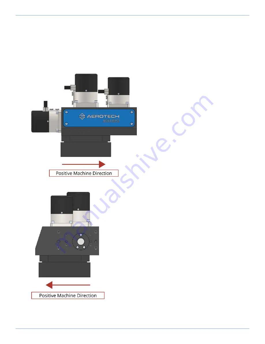
Aerotech stages are configured to have positive and negative "machine" directions. The machine
direction defines the phasing of the feedback and motor signals and is dictated by the stage wiring
(refer to
for Motor and Feedback phasing information). Programming direction of a
stage is set by the controller that is used to move the stage. Programming direction is typically
selectable in the controller, while machine direction is hardwired in the stage.
Figure 3-1:
Galvo X-Axis Machine Direction (front)
Figure 3-2:
Galvo Y-Axis Machine Direction (side)
3.4. Limits, Marker, and Machine Direction
AGV-SPO Hardware Manual
36
www.aerotech.com
Содержание AGV-SPO Series
Страница 1: ...Revision 2 00 AGV SPO Single Pivot Point Galvo Scanner HARDWARE MANUAL...
Страница 6: ...This page intentionally left blank List of Tables AGV SPO Hardware Manual 6 www aerotech com...
Страница 12: ...This page intentionally left blank Laser Shutter AGV SPO Hardware Manual 12 www aerotech com...
Страница 14: ...This page intentionally left blank EU Declaration of Incorporation AGV SPO Hardware Manual 14 www aerotech com...
Страница 16: ...Figure 1 2 Standard AGV SPO Chapter 1 Overview AGV SPO Hardware Manual 16 www aerotech com...
Страница 30: ...This page intentionally left blank 2 6 Water Requirements AGV SPO Hardware Manual 30 www aerotech com...
Страница 38: ...This page intentionally left blank 3 5 Feedback Phasing AGV SPO Hardware Manual 38 www aerotech com...
Страница 46: ...This page intentionally left blank Appendix B Revision History AGV SPO Hardware Manual 46 www aerotech com...


