ABL1500WB-B Hardware Manual
Mechanical Specifications and Installation
2.3. Securing the Stage to the Mounting Surface
The mounting surface must be flat and have adequate stiffness in order to achieve the maximum
performance from the ABL1500WB-B stage. When it is mounted to a non-flat surface, the stage can be
distorted as the mounting screws are tightened. This distortion will decrease overall accuracy. Adjustments
to the mounting surface must be done before the stage is secured.
W A R N I N G : Make sure that all moving parts are secure before moving the ABL1500WB-B.
Unsecured moving parts may shift and cause bodily injury.
D A N G E R : Strong rare-earth magnets are present in the linear motor magnet track. Loose
metal objects (tools, watches, keys, etc.) may cause personal injury and/or damage to the
equipment.
W A R N I N G : The ABL1500WB-B must be mounted securely. Improper mounting can result in
injury and damage to the equipment.
N O T E :
To maintain accuracy, the mounting surface must be flat to within 2.5 µm per 300 mm.
N O T E :
The stage base is precision machined and verified for flatness prior to stage assembly at the
factory. If machining is required to achieve the desired flatness, it should be performed on the mounting
surface rather than the stage base. Shimming should be avoided if possible. If shimming is required, it
should be minimized to improve the rigidity of the system.
Procedure for ABL1500WB-B mounting:
W A R N I N G : Do not attempt to move the carriage of the ABL1500WB-B until the air supply,
detailed in
, has been installed. Moving the stage table without air supplied can
cause permanent damage to the stage.
1. Prepare the mounting surface and bottom of the stage base with precision flatstones to remove any
burrs or high spots.
2. Clean the mounting surface and bottom of the stage with the appropriate cleaners (acetone or isopropyl
alcohol for the stage bottom) and a lint free cloth.
3. Place the stage on the mounting surface.
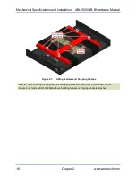
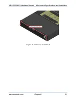
4. Remove the lifting equipment and shipping clamps (
). Save the brackets for future use.
5. Turn on the air supply to the air bearing.
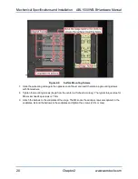
6. Slide the air bearing carriage to one end of travel and compress the bellows. Insert M6 socket head cap
screws with flat washers into the exposed mounting locations. Do not fully tighten at this time, but bring
within 1/4 turn of screw head engagement.
www.aerotech.com
Chapter 2
19
Содержание ABL1500WB-B Series
Страница 1: ...Revision 1 02 00 ABL1500WB B Hardware Manual ...
Страница 6: ...Table of Contents ABL1500WB B Hardware Manual 6 www aerotech com This page intentionally left blank ...
Страница 8: ...Safety ABL1500WB B Hardware Manual 8 www aerotech com This page intentionally left blank ...
Страница 10: ...Declaration of Conformity ABL1500WB B Hardware Manual 10 www aerotech com This page intentionally left blank ...
Страница 48: ...Revision History ABL1500WB B Hardware Manual 48 Appendix B www aerotech com This page intentionally left blank ...

