background image

Hardware Reference Guide

117

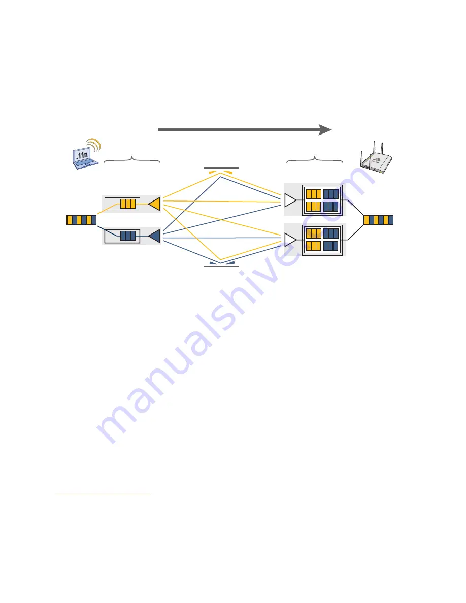
MIMO

recipient’s receive antennas obtain streams from all the transmit antennas. In fact, due to multipath, they 

receive multiple streams from each transmit antenna. The receive antennas pass the spatial streams to the 

digital signal processors in their RF chains, which take the best data from all the spatial streams and 
reassemble them into a single data stream once again (see 

Figure 8

).

Figure 8  2x2 MIMO (2 transmit antennas x 2 receive antennas)

In previous 802.11 standards, access points and clients each employed a single set of components, or RF 

chain, for transmitting or receiving. Although two antennas are often used for diversity, only the one with the 

best signal-to-noise ratio is used at any given moment, and that antenna makes use of the single RF chain 
while the other antenna remains inactive. A significant improvement that MIMO introduces is to permit each 

antenna to have its own RF chain and for all antennas to function simultaneously. For the AP340, for 

example, you can connect up to three antennas per radio and configure the radio to use two or three 
transmit chains and two or three receive chains.

1

 Using two or three transmit and receive chains 

simultaneously increases the amount of data that can flow across the WLAN and accelerates the 

processing of that data at each end of the wireless link.
Another major aspect of MIMO is how it turns multipath signals from a curse to a boon. As a radio signal 

moves through space, some objects reflect it, others interfere with it, and still others absorb it. The receiver 

can end up receiving multiple copies of the original signal, all kind of muddled together. However, the 
digital signal processors in the multiple receive chains are able to combine their processing efforts to sort 

through all the received data and reconstruct the original message. 
Furthermore, because the transmitter makes use of multiple RF chains, there is an even richer supply of 
signals for the receive chains to use in their processing. To set the transmit and receive RF chains for a radio 

profile, enter the following commands:

radio profile <name> transmit-chain { 2 | 3 }

radio profile <name> receive-chain { 2 | 3 }

There are two sets of antennas—three antennas per set—that operate concurrently in two different 

frequency ranges: 2.4 GHz (IEEE 802.11b/g/n) and 5 GHz (IEEE 802.11a/n). Using two different frequency 
ranges reduces the probability of interference that can occur when numerous channels operate within the 

same range. Conceptually, the relationship of antennas and radios is shown in 

Figure 9 on page 118

.

1. The convention for presenting the configuration of transmitting and receiving MIMO RF chains is TxR. For 

example, an AP radio functioning in access mode might be configured to use two RF chains for 

transmitting and three for receiving. In that case, its configuration can be presented as "2x3". In general, 

the number of receive antennas is equal to or greater than the number of transmit antennas.

Transmit 

antennas

Digital signal 

processors

RF chains

RFsignals  

(multipath object)

Receive 

antennas

Digital signal 

processors

RF chains

802.11n wireless client 

with two antennas

AP340 using two 

antennas

Data

Reassembled 

data

Содержание BR200-WP

Страница 1: ...Aerohive Hardware Reference Guide...

Страница 2: ......

Страница 3: ...served Aerohive Networks the Aerohive Networks logo HiveOS HiveAP and HiveManager are trademarks of Aerohive Networks Inc All other trademarks and registered trademarks are the property of their respe...

Страница 4: ...ide describes Aerohive hardware devices including component descriptions installation and mounting instructions wiring diagrams and hardware specifications for each device This guide is a useful resou...

Страница 5: ...2 AP121 and AP141 Platforms 17 AP121 and AP141 Product Overview 18 Ethernet Ports 19 Console Port 20 Reset Button 20 Status Indicator 20 Port LEDs 20 Antennas 21 Mounting the AP121 or AP141 22 Ceilin...

Страница 6: ...uct Overview 42 Ethernet Ports 43 Console Port 43 Reset Button 44 Status LEDs 44 Antennas 44 Mounting the AP320 45 Ceiling Mount 45 Locking the AP320 47 Surface Mount 47 Device Power and Environmental...

Страница 7: ...3 Product Overview 74 Ethernet Ports 75 PoE and PoE Ports 75 PoE Power Management 76 Console Port 77 Reset Button 77 USB Modem Port 77 SFP Uplink Ports 77 Installing or Replacing an SFP Module 78 Cabl...

Страница 8: ...us LEDs 100 Rack Mounting the HiveManager Appliance 101 Device Power and Environmental Specifications 101 Chapter 11 The HiveManager Platform 103 Product Overview 104 Ethernet and Console Ports 105 St...

Страница 9: ...ardware Reference Guide 7 DB9 Console Port Pin Assignments 114 Configuring Antennas 115 Single direction Antennas 115 Omnidirectional Antennas 116 MIMO 116 Using MIMO with Legacy Clients 118 Index 119...

Страница 10: ...Contents 8 Aerohive...

Страница 11: ...r Ethernet that follows the IEEE 802 3af standard or the 802 3at pre standard Optionally they can be powered by an AC DC desktop power adapter This chapter covers the following topics relating to the...

Страница 12: ...nt Description Status indicator The status indicator conveys operational states for system power firmware updates Ethernet and wireless interface activity and major alarms For details see Status Indic...

Страница 13: ...utton the status indicator goes dark as the system reboots Then it glows blue while the device boots and the system performs a self test After the firmware finishes loading and the AP is ready to serv...

Страница 14: ...3 dBi gain All antennas are omnidirectional providing fairly equal coverage in all directions in a cardioid heart shaped pattern around each antenna see Figure 7 on page 116 On the AP110 the two dual...

Страница 15: ...o place prematurely with only one tab in position Figure 4 Attaching the track clip to the ceiling track 3 Twist the track clip until it snaps onto the ceiling track as shown in Figure 5 You can then...

Страница 16: ...and engage the locking mechanism Figure 7 Figure 7 Locking the AP with a Kensington security lock You can also mount the AP to a solid ceiling or the underside of any horizontal object such as a cros...

Страница 17: ...wall from the port side of the AP which is located at the top of the device when it is mounted on a wall You can use a Kensington lock to secure the AP to a stationary object For information see Lock...

Страница 18: ...x 2 H x 6 5 D 16 3 cm W x 4 6 cm H x 16 3 cm D Weight 1 75 lb 0 8 kg Antennas AP110 two dual band omnidirectional 802 11a b g n antennas AP120 two omnidirectional 802 11b g n antennas and two omnidir...

Страница 19: ...per radio The AP121 has four internal antennas and the AP141 has four detachable external antennas two 2 4 GHz and two 5 GHz in both cases Both models have an RJ45 10 100 1000 Ethernet port an RJ45 co...

Страница 20: ...ys operational states for system power firmware updates Ethernet and wireless interface activity and major alarms See Status Indicator on page 20 2 4 and 5 GHz RP SMA connectors AP141 You can connect...

Страница 21: ...onnection details see Power over Ethernet Port Pin Assignments on page 110 The pin assignments in the Ethernet port follow the TIA EIA 568 B standard see Power over Ethernet Port Pin Assignments on pa...

Страница 22: ...te To disable the reset button from resetting the configuration enter this command no reset button reset config enable Pressing the button for 5 seconds will still reboot the AP but pressing it for mo...

Страница 23: ...omnidirectional and provide fairly equal coverage in all directions in a toroidal donut shaped pattern The antennas and connectors are labeled for easy identification and connection and swivel in all...

Страница 24: ...o offers a rail mount kit for 9 16 1 34 cm wide and 15 16 2 38 cm wide recessed tracks for AP330 AP350 AP121 and AP141 models AH ACC 9 16 CLIP 300 100 and AH ACC 15 16 CLIP 300 100 To mount the AP121...

Страница 25: ...on a wall Security tab extension Security screw cavity Tab slot Tab slot V shaped tab V shaped tab Side view Security tab slot Security screw cavity Tab slot Tab slot Security tab extension V shaped...

Страница 26: ...you will need a drilled spanner insert bit for size 6 security screws and a screw driver that will accept the bit The correct bits are available from Aerohive in sets of three for AP121 AP141 AP330 a...

Страница 27: ...D 170 mm W x 41 mm H x 185 6 mm D Weight AP121 11 6 oz 0 36 kg AP141 13 5 oz 0 42 kg Antennas AP121 Two internal omnidirectional 802 11b g n antennas and two internal omnidirectional 802 11a n antenna...

Страница 28: ...Chapter 2 AP121 and AP141 Platforms 26 Aerohive...

Страница 29: ...oE Power over Ethernet that follows the IEEE 802 3at standard This chapter covers the following topics relating to the AP170 device AP170 Product Overview on page 28 Ethernet Port on page 29 Antennas...

Страница 30: ...ing lugs four antenna connectors and a waterproof 10 100 1000 Ethernet connector The device ships with a complete mounting kit see Kit Contents Required Accessories and Tools on page 30 Outdoor antenn...

Страница 31: ...that the antennas are vertical The two 2 4 GHz antennas link to a 2 4 GHz radio for 802 11b g n and the two 5 GHz antennas link to the a 5 GHz radio for 802 11a n The two radios can operate concurren...

Страница 32: ...ot place the AP170 within 8 20 cm of people when using the omnidirectional antennas that ship with the product If you are using a point to point mesh directional antenna do not place the AP170 within...

Страница 33: ...led out Do not locate the AP170 enclosure near overhead power lines or other electric light or power circuits or where it can come into contact with such circuits During installation exercise extreme...

Страница 34: ...e hose strap around the pole and tighten the clamp with a 1 4 2 cm slotted screwdriver or a 5 16 8 mm drive socket or nut driver 5 Connect the grounding cable to the grounding lug on the unit as shown...

Страница 35: ...te ground When attaching the AP170 to a horizontal pole such as the arm of a street light make sure that the face of the device is perpendicular to the Earth for optimal RF coverage Figure 4 Correct a...

Страница 36: ...nut lock washer and flat washer on each bolt to tighten the unit to the surface As you tighten the nuts the flanges on the back of the bolt sleeve will expand in the hole securing the device in place...

Страница 37: ...and antennas are labeled To connect the antennas screw them onto the antenna connectors by hand turning them clockwise until tight It is extremely important to properly ground your device to complete...

Страница 38: ...g onto the threaded connector cover 7 Connect the other end of the Ethernet cable to a PoE injector or Ethernet protector Figure 6 Ethernet housing assembly POE AND ETHERNET PROTECTION In most cases y...

Страница 39: ...necting the Ethernet protection device SKU AH ACC 1G ETH PROT Ethernet Protector Ethernet Protector Ethernet Protector Outdoor PoE injector Indoor PoE Injector PoE Switch Switch Indoors This arrangeme...

Страница 40: ...e of the switch to depress the switch mechanism Hold this position for a minimum of 10 seconds to reset the device See Figure 9 Figure 9 The AP170 internal reset switch 3 Replace the top being careful...

Страница 41: ...antennas 6 05 lb 2 744 kg with antennas and brackets Antennas 4 N type female connectors for external antennas Ethernet connector autosensing 10 100 1000 Base T Mbps compliant with the IEEE 802 3at st...

Страница 42: ...Chapter 3 The AP170 Platform 40 Aerohive...

Страница 43: ...ally in response to the available power in different environments Smart PoE supports the IEEE 802 3af and 802 3at standards This chapter covers the following topics relating to the AP320 AP320 Product...

Страница 44: ...tem power firmware Ethernet interfaces and radios See Status LEDs on page 44 ETH0 PoE port and ETH1 port The AP320 has two 10 100 1000 Mbps RJ45 Ethernet ports ETH0 and ETH1 See Ethernet Ports on page...

Страница 45: ...er Ethernet Port Pin Assignments on page 110 and Figure 3 on page 111 Console Port Through the RJ45 console port you can make a serial connection between your management system and the Aerohive device...

Страница 46: ...ing updated Amber flashing Alarm indicating a firmware issue has occurred Red steady Alarm indicating a hardware issue has occurred ETH0 and ETH1 Dark Ethernet link is down or disabled Green steady 10...

Страница 47: ...ed ceiling grid Using just the mounting plate you can mount the AP320 to any surface that supports its weight 2 lb 0 9 kg Ceiling Mount To mount the AP320 to a track in a dropped ceiling you need the...

Страница 48: ...he ceiling track and swivel them until they snap into place gripping the edges of the track If necessary slide the clips and mounting plate along the track until they are in the spot you want Then tig...

Страница 49: ...r part of the plate make a hole in the wall so that you can pass the cables through to the AP Finally attach the device to the plate and connect the cables as shown in Figure 6 Figure 6 Mounting the A...

Страница 50: ...t 2 lb 0 9 kg Antennas Three omnidirectional 802 11b g n antennas and three omnidirectional 802 11a n antennas Serial port RJ45 bits per second 9600 data bits 8 parity none stop bits 1 flow control no...

Страница 51: ...wer over Ethernet to adjust its power consumption automatically in response the available power in different environments Smart PoE supports the IEEE 802 3af standard and the 802 3at pre standard This...

Страница 52: ...k adapter that is included in the mounting kit and a padlock See Locking the AP340 on page 56 802 11a b g n RP SMA connectors You can connect up to six detachable single band antennas to the male 802...

Страница 53: ...on page 110 and Figure 3 on page 111 Through the RJ45 console port you can make a serial connection between your management system and the Aerohive device For more information about the Console port...

Страница 54: ...onfig enable Pressing the button between 1 and 5 seconds will still reboot the AP but pressing it for more than 5 seconds will not reset its configuration Status LEDs The five status LEDs on the top o...

Страница 55: ...Connect the shorter antennas which support 5 GHz frequencies for IEEE 802 11a n to the connectors on the side panel with the device lock slot For detailed information about how to configure external...

Страница 56: ...te cable quad toggle and locking device you can suspend the device from a beam bracket or any object that can support its weight 3 3 lb 1 5 kg Surface Mount on page 61 Using just the mounting plate an...

Страница 57: ...at the proper distance 2 1 4 or 7 cm to fit through the holes in the mounting plate Insert the mounting plate over the screws attached to the track clips and use the Keps nuts to fasten the plate firm...

Страница 58: ...ameter at its narrowest Plenum Mount To mount the AP340 in the plenum space above a dropped ceiling grid you need the mounting plate hanger clip and a standard 24 wide hanger frame which can be ordere...

Страница 59: ...idge see Figure 9 Figure 9 Clipping the hanger frame onto the track Align the V shaped tabs on the mounting bracket with the tab slots on the bottom of the AP Insert the V shaped tabs into the tab slo...

Страница 60: ...ct one or two Ethernet cables to the network and if not using PoE connect the power cord to a power source 8 Replace the ceiling tile to complete the installation Bird s eye view with the ceiling tile...

Страница 61: ...arrow on its side and then pass it through the loop at the end of the quad toggle 5 Insert the wire rope back through the center hole in the locking device and pull it through the locking device unti...

Страница 62: ...ed While maintaining pressure on the tube adjust the rope until the AP340 is at the height you want When you are satisfied stop pressing against the tube so that it can regain its grip on the rope Fig...

Страница 63: ...t of their connections accidentally Mounting plate AP Wall Orient the mounting plate as shown and attach it to a secure object such as a wall post or beam Use 8 screws for the oblong holes or 10 screw...

Страница 64: ...ight 3 lb 1 36 kg Antennas Three omnidirectional 802 11b g n antennas and three omnidirectional 802 11a n antennas Serial port RJ45 bits per second 9600 data bits 8 parity none stop bits 1 flow contro...

Страница 65: ...up to 450 Mbps per radio The AP330 has internal antennas and the AP350 has detachable external antennas They both have dual 10 100 1000 Ethernet ports for link aggregation or link redundancy Their sys...

Страница 66: ...67 Console port You can access the CLI by making a serial connection to the RJ45 console port For details see Console Port on page 65 Power connector The 12 volt DC power connector 2 0 amps is one of...

Страница 67: ...Interfaces on page 112 The pin assignments in the Ethernet ports follow the TIA EIA 568 B standard see Figure 3 on page 111 and accept standard cat3 cat5 cat5e or cat6 Ethernet cable Because the ports...

Страница 68: ...ferent states of activity The meanings of the colors are as follows Dark There is no power or the status indicator is disabled Blue solid The device is booting up or there is no backhaul link flashing...

Страница 69: ...d horizontally or vertically the articulated antennas hinge and swivel The non articulated antennas are intended for wall installations and have a fixed orientation in the same direction as the antenn...

Страница 70: ...aped tabs and the security tab extension on the rail mount with the two tab slots and the security screw cavity on the underside of the AP and then push the AP upward until it clicks into place as sho...

Страница 71: ...ss the AP upward until it snaps into place 4 Security tab extension Security screw cavity Tab slot Tab slot V shaped tab V shaped tab side view Security screw cavity Tab slot Tab slot Security tab ext...

Страница 72: ...r that will accept the bit The correct bits are available from Aerohive in sets of three AH ACC SEC BIT 330 AP350 3PK If you use the slotted screw you can install it with a standard flat blade screwdr...

Страница 73: ...2 11b g n antennas and three omnidirectional 802 11a n antennas Serial port RJ45 bits per second 9600 data bits 8 parity none stop bits 1 flow control none Ethernet ports Eth0 autosensing 10 100 1000B...

Страница 74: ...Chapter 6 AP330 and AP350 Platforms 72 Aerohive...

Страница 75: ...orts on page 75 PoE and PoE Ports on page 75 PoE Power Management on page 76 Port Priority on page 76 Console Port on page 77 Reset Button on page 77 USB Modem Port on page 77 SFP Uplink Ports on page...

Страница 76: ...the SR series switches and configuration settings refer to HiveManager Help Power LED The Power LED is located on the left side of the front panel This LED indicates when the device is powered on See...

Страница 77: ...ports are shut down to maintain the 802 3 power budget these ports will still function as standard Ethernet ports Speed LED mode When you select Speed mode the port LEDs indicate the port operating sp...

Страница 78: ...management the maximum power delivered by each port is determined by the power threshold 802 3af or 802 3at that is configured on that port If more power is required than the ports can deliver the sw...

Страница 79: ...p to the ETH0 WAN interface however for locations where an Ethernet connection to the WAN is not possible you can use the USB modem as the primary and only interface to the WAN Before you can use a mo...

Страница 80: ...in connectors and can cause connection problems Use a dry recommended or wet cleaning process to clean connectors using either lint free wipes or lint free swabs Lightly wipe the connectors to clean t...

Страница 81: ...this section Figure 2 Temperature and fan information display in HiveManager Changing the Temperature and Fan Speed Alarm Thresholds You can change the threshold for the alarms in HiveManager To do t...

Страница 82: ...k Green solid Port is active but there is no traffic Green flashing Port is actively passing traffic With Speed mode selected Dark No power to port Green Port is operating at 1000 Mbps Amber Port is o...

Страница 83: ...nt Adequate ventilation is critical for switch operation Install your devices in a properly ventilated equipment rack or for tabletop installations leave some clear space at the sides of the switch so...

Страница 84: ...weight 16 lb 7 26 kg Ethernet ports 24 IEEE 802 3 10BASE T IEEE 802 3u 100BASE TX and IEEE 802 3ab 1000BASE T compliant 10 100 1000 Mbps RJ45 Ethernet ports Four SFP copper or fiber uplink ports USB...

Страница 85: ...P and DNS services centralized management and firewall and VPN security This chapter covers the following topics relating to the BR100 router Product Overview on page 84 Radio and Antennas on page 86...

Страница 86: ...er hardware components Each component is described in Table 1 BR100 router component descriptions Figure 1 The BR100 router hardware components Table 1 BR100 router component descriptions Component De...

Страница 87: ...description the ports to which it applies and optional security and filtering rules For information about how to configure a LAN profile refer to HiveManager Help Reset button The reset button allows...

Страница 88: ...the 3G wireless network AT T Shockwave Sierra Wireless USBConnect 308 to connect to the 3G wireless network Verizon Pantech UML290 to connect to the 4G LTE network Before you can use a modem with an A...

Страница 89: ...g a firmware upgrade Do not turn the device off while the LED is flashing White steady The device has made a CAPWAP connection to HiveManager and is operating properly White flashing Device is operati...

Страница 90: ...78 g Antennas Two embedded single band omnidirectional 802 11b g n antennas Ethernet ports One IEEE 802 3 10BASE T and IEEE 802 3u 100BASE TX compliant 10 100 Mbps RJ45 Fast Ethernet WAN port Four IEE...

Страница 91: ...ere are two BR200 models the BR200 and the BR200 WP This chapter covers the following topics relating to Aerohive BR200 series routers Product Overview on page 90 Radio and Antennas on page 91 Etherne...

Страница 92: ...0 four LAN ports ETH1 through ETH4 a Console Port and a USB port for WAN connection redundancy The BR200 series routers support up to 16 SSIDs BR200 WP only 16 VLANs 16 networks and 64 user profiles a...

Страница 93: ...t through and crossover Ethernet cables automatically Use the yellow Ethernet cable that ships with the device to connect your router from the WAN port to a cable or DSL modem or other Internet device...

Страница 94: ...ical interface For this reason you can apply multiple LAN profiles one for each of the four ports In HiveManager a LAN profile consists of a name description the ports to which it applies and optional...

Страница 95: ...200 WP PoE LAN Ports On BR200 WP routers the ETH1 PoE and ETH2 PoE ports can provide PoE Power over Ethernet to PDs powered devices such as VoIP phones wireless access points and network cameras These...

Страница 96: ...Dark No link Green steady The Ethernet link is up but inactive at 1000 Mbps Green flashing The Ethernet link is up and active at 1000 Mbps Amber steady The Ethernet link is up but inactive at 10 100 M...

Страница 97: ...ctional 802 11b g n antennas Ethernet ports One IEEE 802 3 10BASE T IEEE 802 3u 100BASE TX and IEEE 802 3ab 1000BASE T compliant 10 100 1000 Mbps RJ45 Fast Ethernet WAN port Four IEEE 802 3 802 3u and...

Страница 98: ...Chapter 9 BR200 and BR200 WP Routers 96 Aerohive...

Страница 99: ...Specifications on page 101 SAFETY GUIDELINES Follow the guidelines in this section the ensure the safety of personnel and equipment Table 1 explains the meaning of caution and warning icons Table 2 l...

Страница 100: ...promised Electrostatic discharge ESD can damage equipment and impair electrical circuitry ESD damage occurs when electronic components are improperly handled and can result in complete or intermittent...

Страница 101: ...ackets Mounting brackets allow you to install the chassis in a front or mid mount position in a standard 19 48 26 cm equipment rack Console port The RJ45 Console port allows you to make a console conn...

Страница 102: ...the HiveManager appliance indicate the status for power and hard disk drive activity through their color dark or green and illumination patterns steady glow or blinking The meanings of the color and...

Страница 103: ...in the rail use two screws and washers per bracket 3 Tighten the screw until it is secure 4 Repeat steps 2 and 3 to secure the other side of the HiveManager Appliance to the rack DEVICE POWER AND ENVI...

Страница 104: ...wer factor corrector Input 100 240 VAC Output 250 watts Power supply cord Standard three conductor SVT 18AWG cord with an NEMA5 15P three prong male plug and three pin socket Environmental Specificati...

Страница 105: ...nagement of up to 500 devices Profile based configurations that simplify the deployment of large numbers of devices Scheduled firmware upgrades on devices by location Exportation of detailed informati...

Страница 106: ...The status LEDs convey operational states for the system power and hard disk drive For details see Status LEDs on page 105 MGT and LAN Ethernet ports The MGT and LAN Ethernet ports are compatible wit...

Страница 107: ...emulation program such as Tera Term Pro a free terminal emulator or Hilgraeve Hyperterminal provided with Windows operating systems The serial connection settings are as follows Bits per second 9600...

Страница 108: ...pending on the layout of your equipment rack you might need to mount the HiveManager in reverse To do that move the brackets to the left and right sides near the rear before mounting Figure 3 Mounting...

Страница 109: ...16 W x 1 3 4 H x 15 13 16 D 42 7 cm W x 4 4 cm H x 40 2 cm D Weight 13 75 lb 6 24 kg Serial port male DB9 RS 232 port bits per second 9600 data bits 8 parity none stop bits 1 flow control none USB por...

Страница 110: ...Chapter 11 The HiveManager Platform 108 Aerohive...

Страница 111: ...RT PIN ASSIGNMENTS The following sections contain pin assignments and wiring information for standard and PoE power over Ethernet Ethernet ports for Aerohive devices Standard non PoE Ethernet Port Pin...

Страница 112: ...raight through or crossover Ethernet connections Likewise they can automatically adjust to 802 3af Alternative A and B power delivery methods Furthermore when the Alternative A method is used the port...

Страница 113: ...igher If the available power drops to a range between 18 and 20 W the device disables its ETH1 interface assuming that it is drawing power through its ETH0 interface If it is drawing power solely thro...

Страница 114: ...d interface called agg0 The aggregate interface effectively doubles the bandwidth that each physical interface has when used individually In this configuration both Ethernet ports actively forward tra...

Страница 115: ...uses the following logic to choose which interface to use in its default route If there is an Ethernet interface and a wireless interface in backhaul mode the AP uses the Ethernet interface in its de...

Страница 116: ...yperterminal provided with Windows operating systems The serial connection settings are Bits per second 115 200 Data bits 8 Parity none Stop bits 1 Flow control none The pin assignments in the male DB...

Страница 117: ...ines the coverage pattern Single direction Antennas The most common external antennas are directional patch antennas that provide coverage in a single direction Most commonly they have a transmission...

Страница 118: ...e a problem in environments with high ceilings Figure 7 Omnidirectional antenna radiation patterns MIMO MIMO Multiple In Multiple Out is a major WLAN advancement introduced in the IEEE 802 11n standar...

Страница 119: ...t it others interfere with it and still others absorb it The receiver can end up receiving multiple copies of the original signal all kind of muddled together However the digital signal processors in...

Страница 120: ...11a b g client traffic Although 802 11a b g client traffic can benefit somewhat from an 802 11n access point using MIMO supporting such legacy clients along with 802 11n clients can have a negative i...

Страница 121: ...AP141 17 25 antenna connectors 18 antennas 21 console port 19 20 environmental specifications 25 Ethernet ports 19 external antenna alignment 21 hardware specifications 25 LEDs 20 locking 24 mounting...

Страница 122: ...ies 89 95 console port 91 92 device and enclosure specifications 95 device status LED 91 94 environmental specifications 95 Ethernet ports 91 92 hardware specifications 95 link status LED 91 94 lockin...

Страница 123: ...switch 73 82 cabling an SFP module 78 change temperature and fan speed alarm thresholds 79 cleaning SFP fiber ports and connectors 78 console port 74 77 device and enclosure specifications 82 environm...

Страница 124: ...Index 122 Aerohive...

Отзывы: