background image

16

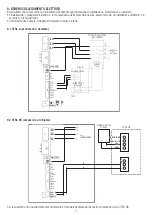
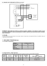
For functionalities, refer to the dedicated manual of the CTRL-HS touch control panel.

9.2 CTRL-HS (accessory on request)

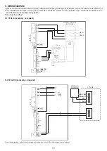
9. WIRING DIAGRAM

• Make sure that the mains supply to the unit is disconnected before performing any installation, service, maintance or electrical work!

• The installation and service of the unit and complete ventilation system must be performed by an authorized installer and in 

accordance with local rules and regulations.

• Fan must be earthed. 

9.1 CTRL-A (accessory on request)

POTENTIOMETER

L3

L2

L1

400 Vac

3 ph.

50/60 Hz

COIL

230V

BIPOLAR

SWITCH

230V

+

U

-

CTRL - A

EXTERNAL CONTACTOR 

(NOT SUPPLIED)

YELLOW - GREEN

BROWN

BLACK

GREY

L3

L2

L1

3 ph.

POWER

SUPPLY

4-core power cable

6-core control cable

EXTERNAL

POTENTIOMETER

≥10kΩ

(NOT SUPPLIED)

YELLOW

GREEN

WHITE

GREY

MODBUS B

BROWN

PINK

MODBUS A

B

A

-

+

+

-

EXTERNAL DC

POWER SUPPLY

VAC/+

GND

3 ph. 
POWER
SUPPLY

VAC/-

CAN+/A+/1B

CAN-/B-/GND

CTRL-HS

GND

+10Vout

GND

Vin 2

Vin 1

COMMON

IN 4A

IN 3A

IN 2A

IN 1A

NO
NC
COM

L3
L2
L1

GND-iso

485 +

485 -

TERM

TERM
SCH

PT01

PT02

GND

+10Vout

GND

Vin 2

Vin 1

COMMON

IN 4A

IN 3A

IN 2A

IN 1A

NO
NC
COM

L3
L2
L1

GND-iso

485 +

485 -

TERM

TERM
SCH

PT01

PT02

L3

L2

L1

Содержание WHS Series

Страница 1: ...Manuale Specifico 2 Specific Manual 11 IT EN WHS ...

Страница 2: ...e Manutenzione è necessario prestare particolare attenzione alle seguenti note controllare annualmente il fissaggio e il serraggio di dadi e viti Tabella 1 Utilizzare i valori riportati in tabella per il serraggio di tutta la viteria il prodotto non deve lavorare in condizioni di ventosità elevata max 6m s e o in ambienti dove tale ventosità è frequente assicurarsi che la struttura sulla quale vie...

Страница 3: ...717 10 6 38 WHS500 5 105 1 1 366 152319 258791 16 0 215412 365986 11 3 46 WHS600 5 84 1 4 302 178738 303677 16 6 252774 429464 11 7 64 5 DATI 400Vac 50Hz 7 COMPONENTI Il ventilatore è consegnato in due kit imballati separatamente il KIT MOTORE include corpo principale Fig I 1 tubolare standard lunghezza 800mm Fig I 2 2x piastre di fissaggio al soffitto Fig I 3 e Fig VI 2x set di fissaggio 4x vite ...

Страница 4: ...sione dell aria dovrebbero scaricare lontano dal ventilatore i punti di estrazione dell aria che potrebbero creare depressione devono essere posizionati ad una distanza pari a 1 5 volte il diametro del ventilatore durante il montaggio segnare sul pavimento un cerchio tratteggiato per avvertire eventuali persone presenti nella struttura della posizione del ventilatore Comporre il set cavi di sicure...

Страница 5: ...bella 1 Montare i cappucci in plastica 14 sui dadi autobloccanti Fissare l assieme al soffitto trave sfruttando gli otto fori delle piastre di fissaggio 3 e collegare il cavo di sicurezza al soffitto trave utilizzando i morsetti 18 La viteria di fissaggio al soffitto trave non è fornita in dotazione Rimuovere dal corpo principale 1 le tre staffe di appoggio per il trasporto togliendo le relative v...

Страница 6: ...one posta in prossimità della macchina Dimensionare opportunamente i cavi tenendo conto della distanza tra macchina e punto di alimentazione La realizzazione della rete di alimentazione e il collegamento ad essa devono essere realizzate da un installatore qualificato ed autorizzato in accordo con le prescrizioni vigenti nel paese di utilizzo della macchina Fig X Fig XI Fig XII 23 Fig XII Scatola d...

Страница 7: ...9 1 CTRL A accessorio a richiesta Per le specifiche di funzionamento fare riferimento al manuale dedicato del pannello di comando touch CTRL HS 9 2 CTRL HS accessorio a richiesta YELLOW GREEN BROWN BLACK GREY L3 L2 L1 3 ph POWER SUPPLY 4 core power cable 6 core control cable EXTERNAL POTENTIOMETER 10kΩ NOT SUPPLIED YELLOW GREEN WHITE GREY MODBUS B BROWN PINK MODBUS A B A ALIMENTATORE DC ESTERNO VA...

Страница 8: ...e 1 10 PULIZIA La macchina IP55 può essere lavata con uno getto d acqua In questo caso si raccomanda di forare la copertura mozzo per consentire all acqua di defluire 11 2 Registri Modbus Registri di Ingresso Questi registri sono di SOLA LETTURA e possono essere letti usando la funzione 04 READ INPUT REGISTERS Indirizzo Registro Descrizione Dimensione Word Tipo di dato U M dato nel registro Esempi...

Страница 9: ...ontrollare la tensione di alimentazione controllare il cablaggio di alimentazione 4 33 Sotto tensione tensione di alimentazione inferiore a 212Vac tensione bus DC inferiore a 300V con motore in funzione valore istantaneo Controllare la tensione di alimentazione controllare il cablaggio di alimentazione 4 113 Temperatura dell elettronica superiore a 85 C controllare il registro di ingresso 15 Contr...

Страница 10: ...sclusiva del fabbricante DICHIARAZIONE DI INCORPORAZIONE In accordo alla Direttiva Macchine 2006 42 EC Dichiariamo qui di seguito che I prodotti della gamma Ventilatori da soffitto serie WHS MODELLI WHS400 WHS500 WHS600 sulla base del loro progetto e costruzione come quasi macchine sono progettati in conformità con I Requisiti Essenziali di Salute e Sicurezza EHSRs dell ALLEGATO I sezioni 1 1 2 In...

Страница 11: ...nual special attention should be paid to the following warning notes fixing check inspect and eventually retighten all the fixing annually windy conditions fans should not operate in case of strong wind 6m s and should not be installed in places where it is frequently windy weight it is recommended that the building structure is capable to bear approx twice the weight of the fan as well as a torqu...

Страница 12: ...ecurity wire 4x Ø3mm stabilizing wires with turnbuckle Fig X 21 5x 5mm snap hooks Fig X 22 and 8x clamp Fig XIII 23 for the stabilizing wires BLADES KIT incudes five blades Fig VIII 13 The electrical wire type Fig III 15 not supplied must comply with the local regulations of the electric system and must have the following features 4 core supply power cable section 1mm2 6 core control cable section...

Страница 13: ...not be located within 1 5 times the fan diameter when mounting the fan mark the floor with a large crosshatched circle to alert people of the overhead fan location Compose the security cable set consisting of Ø5mm wire of 2 5m lenght 16 0 33t shackle 20 Ø5mm wire of 0 35m lenght with two rings 17 and the 7mm snap hook 19 Insert the security wire 16 and electric cables 15 not supplied into the down...

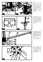
Страница 14: ...nge bolts 8 spring washers 10 and locknuts 9 Tighten the screws making reference to table 1 Mount the plastic caps 14 on the locknuts Fix the assembly to the ceiling beam through the 8 holes on the brackets 3 fix the security wire to the ceiling beam using the clamps 18 Fixing screws plugs are not supplied 13 10 9 14 8 Fig VIII 18 Fig VII Staffe di appoggio per il trasporto in imballo Fig IV Fig V...

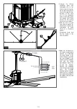
Страница 15: ...t supplied to be placed near the ventilation unit Size the cables appropriately taking into account the distance between the ventilation unit and the power supply point The complete electrical system must be carried out by a qualified and authorized installer in accordance with the local requirements 45 Fig XI 22 22 21 21 Fig X 23 Fig XII Scatola di derivazione Non fornita Linee potenza e controll...

Страница 16: ... CTRL A accessory on request POTENTIOMETER L3 L2 L1 400 Vac 3 ph 50 60 Hz COIL 230V BIPOLAR SWITCH 230V U CTRL A EXTERNAL CONTACTOR NOT SUPPLIED YELLOW GREEN BROWN BLACK GREY L3 L2 L1 3 ph POWER SUPPLY 4 core power cable 6 core control cable EXTERNAL POTENTIOMETER 10kΩ NOT SUPPLIED YELLOW GREEN WHITE GREY MODBUS B BROWN PINK MODBUS A B A EXTERNAL DC POWER SUPPLY VAC GND 3 ph POWER SUPPLY VAC CAN A...

Страница 17: ...isters are READ ONLY and can be read using the function 04 READ INPUT REGISTERS Register Address Description Dimension Word Data Type U M data on the register Example Register value Real value 3 Measured speed 1 ushort 0 1rpm 490 49rpm 10 Alarm 1 1 ushort See table 11 3 17 Alarm 2 1 ushort See table 11 3 YELLOW GREEN BROWN BLACK GREY L3 L2 L1 3 ph POWER SUPPLY 4 core power cable 6 core control cab...

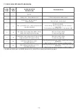
Страница 18: ...ing motor running Check power supply voltage check power supply wiring 4 33 Under voltage supply voltage below 212Vac DC bus voltage below 300V during motor running Check power supply voltage check power supply wiring 4 113 Electronics temperature over 85 C check input register 15 Check if operating temperature is above rated maximum operating temperature Check mechanical load for anomalies e g di...

Страница 19: ...ion is issued under the sole responsibility of the manufacturer UE DECLARATION OF INCORPORATION In accordance with the Machinery Directive 2006 42 EC We herewith declare that the following range WHS series ceiling fans MODELS WHS400 WHS500 WHS600 on the basis of its design and construction of partly completed machines is designed in compliance with the Essential Health and Safety Requirements EHSR...

Страница 20: ...egale Registered office via Mario Calderara 39 41 25018 Montichiari Bs C F e P IVA VAT 03369930981 REA BS 528635 Tel 39 030 674681 Fax 39 030 6872149 www aerauliqa it www aerauliqa com info aerauliqa it Aerauliqa S r l si riserva il diritto di modificare apportare migliorie ai prodotti e o alle istruzioni di questo manuale in qualsiasi momento e senza preavviso Aerauliqa S r l reserves the right t...

Отзывы: