15
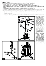
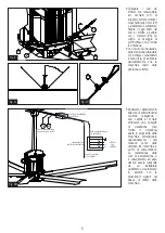
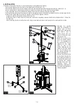
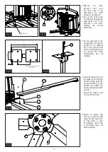
• Connect the Ø3mm
stabilizing wires with
turnbuckle (21) to the
motor support using the
5mm snap-hooks (22) to
the motor support holes.
Securely fix the other
end of the stabilizing
wires to the ceiling using
the clamps (23). Fixing
screws for the ceiling/
beam are not supplied.
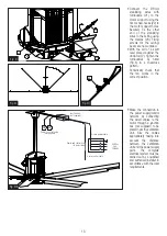
• With the aid of a spirit
level placed against the
downrod (2), tighten the
turnbuckles by hand
(Fig.X) in a crisscross
pattern.
Periodically check that
the fan works in the
correct position.
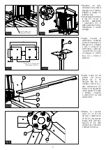
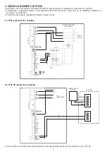
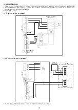
• Make the connection to
the power supply/control
network by connecting
the wired cables to the
motor through a junction
box (not supplied) to be
placed near the ventilation
unit. Size the cables
appropriately taking into
account the distance
between the ventilation
unit and the power supply
point. The complete
electrical system must be
carried out by a qualified
and authorized installer, in
accordance with the local
requirements.
45°
Fig. XI
22
22
21
21
Fig. X
23
Fig. XII
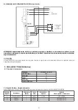
Scatola di derivazione
(Non fornita)
Linee potenza e controllo
(da allestire)
Cavi per alimentazione
e controllo
(Non forniti)
15
15
L1
L2
L3
400 Vac
3 ph.
50/60 Hz
Cavo di alimentazione
a 4 conduttori
Cavo di controllo
a 6 conduttori
Fig. XIII
Fig. X
Fig. XI
Fig. XII
23
Fig. XII
Fig. XIII
Power / control cable
(not supplied)
Power and control lines
(to be installed)
6-core control cable
4-core power cable
400Vac
3ph.
50/60Hz
Junction box
(not supplied)
15 15


