- 1 -
www.advateklights.com
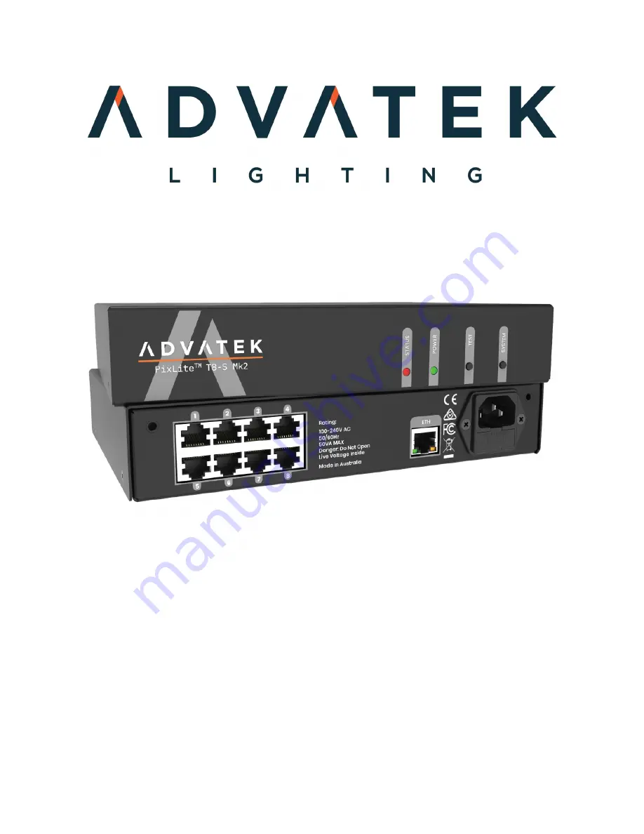
PixLite T8-S Mk2 User Manual V210222
PixLite T8-S Mk2 User Manual
Hardware Rev 1.0
Страница 1: ...1 www advateklights com PixLite T8 S Mk2 User Manual V210222 PixLite T8 S Mk2 User Manual Hardware Rev 1 0...
Страница 2: ...onnections 15 5 1 Supplying Power 15 5 2 Control Data 15 5 3 Connecting the Transmitter to Receivers 16 5 4 Expanded Mode 17 6 Network Configuration 18 6 1 Network Layout 18 6 2 IP Addressing 19 6 2 1...
Страница 3: ...er Manual V210222 9 2 Mechanical Specifications 26 9 3 Fault Protection 27 10 Troubleshooting 28 10 1 LED Codes 28 10 2 No Power Status LEDs On 28 10 3 No Pixel Control 29 10 4 Other Issues 29 10 5 Re...
Страница 4: ...als are then converted back to signals suitable for pixels This system allows the user to distribute a large number of pixels from a centralized pixel controller easily without needing to worry about...
Страница 5: ...mains socket outlet with a protective earthing connection The plug on the power supply cord is used as the disconnect device so the socket outlet shall be easily accessible Power to the device is pro...
Страница 6: ...ting holes on the bottom side of the controller Ensure the countersunk holes on the mounting plates are aligned with the controller s mounting holes 2 Assemble the mounting plates onto the controller...
Страница 7: ...7 www advateklights com PixLite T8 S Mk2 User Manual V210222 screws should be a pan head type 4mm in thread diameter and at least 10mm long Figure 2 Mounting Plates Assembled to Wall Ceiling...
Страница 8: ...e drill four holes in your mounting plate with a 4 5mm size drill as shown in Figure 3 below Figure 3 Drilling Location Guide 2 From the bottom side of the panel use four M4 machined thread screws to...
Страница 9: ...9 www advateklights com PixLite T8 S Mk2 User Manual V210222 Figure 4 Controller Assembled onto Panel...
Страница 10: ...1RU height The first option is to mount a single controller in the middle of a rack slot as shown in Figure 5 below Use optional mounting kit part number MNT0201 for this configuration Figure 5 Single...
Страница 11: ...oller Configuration 1 Using the six supplied countersunk screws assemble the two brackets to the controller as shown in Figure 7 below Figure 7 Single Brackets Assembled to Controller 2 Assemble the c...
Страница 12: ...r Manual V210222 Figure 8 Nuts Fitted to Rack Figure 9 Single Controller Assembled to Rack 4 3 2 Dual Controller Configuration 1 Using the twelve supplied countersunk screws assemble the two brackets...
Страница 13: ...Mk2 User Manual V210222 Figure 10 Dual Brackets Assembled to Controller 2 Assemble the controller to the 19 rack using the supplied pan head screws washers and nuts as shown in Figure 11 and Figure 1...
Страница 14: ...14 www advateklights com PixLite T8 S Mk2 User Manual V210222 Figure 12 Dual Controller Assembled to Rack...
Страница 15: ...d be connected to the AC mains supply The IEC input socket on the rear of the enclosure as shown in Figure 13 below also contains an accessible compartment with 250V 1A glass fuse F1A L 250V Figure 13...
Страница 16: ...can be safely used in excess of 300m Figure 15 Correct equipment to use The PixLite T8 S Mk2 may be connected to two different types of receivers The first is the PixLite R2F which has 2 full pixel o...
Страница 17: ...pixel outputs 32 but half as many pixels per output can be run The PixLite R4D receiver was specifically designed to take advantage of this mode and you will always need to use the PixLite T8 S Mk2 in...
Страница 18: ...shows a typical network topology for the PixLite T8 S Mk2 controller s LAN Installations using multicast sACN will benefit from the use of IGMP Snooping enabled network equipment when there are more...
Страница 19: ...examples 6 2 IP Addressing 6 2 1 Using a Router Routers have a DHCP server in them this means they will tell a device plugged into them what IP address to use if asked DHCP is always enabled by defaul...
Страница 20: ...to 192 168 0 50 This means your PC s IP should be 192 168 0 xxx where xxx is anything between 1 and 254 other than 50 The subnet mask on your PC should be set to 255 255 255 0 Note The Advatek Assista...
Страница 21: ...n the Advatek Assistant it can be forced to its default IP A simple procedure can be employed on power up 1 Hold down the Test button and power up the controller 2 After a few seconds release the butt...
Страница 22: ...onfiguration If the pixels are not controllable then make sure you have selected the correct pixel IC type in the Advatek Assistant under the LEDs tab 7 3 Outputs Each of the 8 controller RJ45 output...
Страница 23: ...cle Outputs will cycle automatically through the red green blue and white colours at fixed intervals Pressing the but ton moves to the next mode Red Solid Red Green Solid Green Blue Solid Blue White S...
Страница 24: ...tandard Update 1 Open the Advatek Assistant Click Search and once the desired controller appears in the main window double click on it 2 A configuration window will appear Click on the Misc tab and th...
Страница 25: ...otloader mode It is now ready for a firmware update The controller will default to an IP address of 192 168 0 50 in this mode so you must ensure your PC performing the recovery is on a network in the...
Страница 26: ...te T8 S Mk2 controller Parameter Value Range Units Input Voltage Range 100 240 50 60 Hz V AC Max Current Consumption 500 mA Ambient Operating Temperature 10 to 60 C 9 2 Mechanical Specifications The P...
Страница 27: ...arious types of faults This makes the device extremely robust and reliably able to withstand installation and operation even in harsh environments ESD protection is present on all data line outputs an...
Страница 28: ...unning Off Solid Main application not running Solid Off Main application not running Alternate flashing Alternate flashing Bootloader mode Off Off No power Please refer to the table below for conditio...
Страница 29: ...nd other help you should refer to our online knowledgebase here www advateklights com knowledge base If you can t resolve your problem with the help of our knowledgebase you can send an e mail to supp...
Страница 30: ...to comply with the limits for a Class A digital device pursuant to part 15 of the FCC Rules These limits are designed to provide reasonable protection against harmful interference when the equipment...