11
UNO-3272G User Manual
Chapter 2
H
/W Installation
2.2
Jumpers
Configure the UNO-3272G to match the needs of your application by setting jumpers.
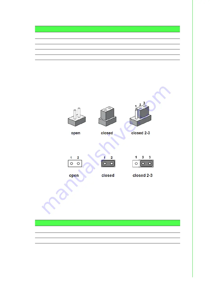
To close a jumper, you connect the pins with the clip. To open a jumper, you remove
the clip. Sometimes a jumper will have three pins, labeled 1, 2 and 3. In this case you
would connect either pins 1 and 2, or 2 and 3.
The jumper settings are schematically depicted in this manual as follows.
A pair of needle-nose pliers may be helpful when working with jumpers. If you have
any doubts about the best hardware configuration for your application, contact your
local distributor or sales representative before you make any changes. Generally, you
simply need a standard cable to make most connections.
2.2.1
Jumper list
Table 2.3: COM Connector
Location
Function
CN2
COM1/COM2
CN3
COM3COM4
CN4
MIC IN
CN6
LINE Out
Table 2.4: Jumper List (motherboard)
Location
Function
CN1
Clear CMOS
CN14
System AT/ATX mode option
Содержание UNO-3272G Series
Страница 16: ...UNO 3272G User Manual 6...
Страница 17: ...Chapter 2 2 H W Installation This chapter introduces external IO and the installation of UNO 3272G hardware...
Страница 43: ...Chapter 3 3 AMI BIOS Setup This chapter introduces how to set BIOS configuration data...
Страница 57: ...47 UNO 3272G User Manual Chapter 3 AMI BIOS Setup 3 2 3 Chipset...
Страница 63: ...53 UNO 3272G User Manual Chapter 3 AMI BIOS Setup...


