21 PPC-3150SW/3180SW/324W-PN4 User Manual
C
ha
pte
r 2
Sy
ste
m
In
sta
lla
tio
n a
nd
S
etu
p
2.
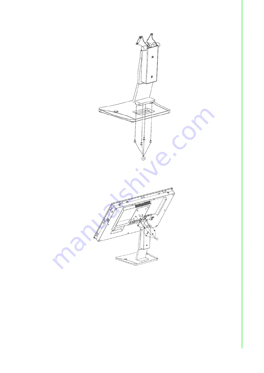
Use four M4 x 8L screws to secure the base plate to the mount stand.
Figure 2.14 Securing the VESA Mount Base
3.
Use four M4 x 6L screws to secure the mount stand to the VESA mount bracket.
Figure 2.15 Securing the VESA Mount Bracket
Содержание PPC-3150SW
Страница 8: ...PPC 3150SW 3180SW 324W PN4 User Manual viii...
Страница 11: ...Chapter 1 1 General Information Introduction Specifications Dimensions...
Страница 33: ...Chapter 3 3 Jumper Setting Motherboard Layout Jumpers and Connectors External COM Ports and Pin Definitions...
Страница 38: ...PPC 3150SW 3180SW 324W PN4 User Manual 28...
Страница 39: ...Chapter 4 4 Software Setup Driver Installation BIOS Setup Program...
Страница 50: ...PPC 3150SW 3180SW 324W PN4 User Manual 40 2 Set Wake on Ring to enabled...
Страница 51: ...Appendix A A Watchdog Timer Programming...


