17
PCIE-1840 User Manual
Chapter 3
S
ignal Connections
3.3.2.2
Analog Trigger
You can configure the PCIE-1840 analog trigger circuitry to monitor any input chan-
nel from which you acquire data. Choosing an input channel as the trigger channel
does not influence the input channel acquisition capabilities.
The trigger circuit generates an internal digital trigger based on the input signal and
the defined trigger levels. For example, you can configure the device to start acquir-
ing samples after the input signal crosses a specific threshold. PCIE-1840 offers sev-
eral analog triggering modes, including analog edge, analog edge with hysteresis,
and window triggering.
Analog trigger connections are the same as
Analog Input Connections
, please
refer to differential input (Figure 3.3) or pseudo-differential input (Figure 3.4).
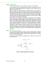
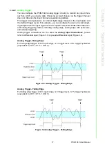
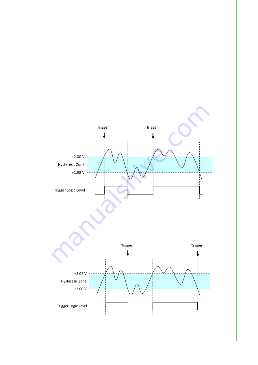
Analog Trigger- Rising Edge
For rising edge trigger, ±10 V input range, +2 V trigger level, 0.1% trigger hysteresis
(equivalent to 20 V × 0.1% = 0.02 V).
Figure 3.3 Analog Trigger - Rising Edge
Analog Trigger- Falling Edge
For falling edge trigger, ±10 V input range, +2 V trigger level, 0.1% trigger hysteresis
(equivalent to 20 V × 0.1% = 0.02 V).
Figure 3.4 Analog Trigger - Falling Edge
Содержание PCIE-1840
Страница 1: ...User Manual PCIE 1840 4 ch 16Bit 125 MS s High Speed Data Acquisition PCI Express Card ...
Страница 4: ...PCIE 1840 User Manual iv ...
Страница 12: ...PCIE 1840 User Manual 6 ...
Страница 13: ...Chapter 2 2 Installation ...
Страница 18: ...PCIE 1840 User Manual 12 ...
Страница 26: ...PCIE 1840 User Manual 20 ...
Страница 27: ...Appendix A A Specifications ...
Страница 35: ...Appendix B B Block Diagram ...


