eWorx SE500 Series Switches
:
50
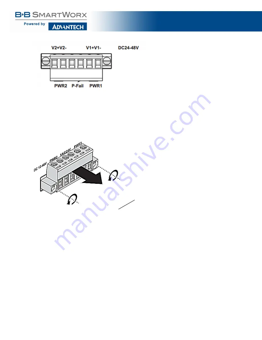
Figure 26: Terminal Receptor: Power Input Contacts for PoE models
To wire the power inputs:
Make sure the power is not connected to the switch or the power converter before proceeding.
1.
Loosen the screws securing terminal block to the terminal block receptor.
2.
Remove the terminal block from the switch.
Figure 27: Removing a Terminal Block
3.
Insert a small flat-bladed screwdriver in the V1+/V1- wire-clamp screws, and loosen the
screws.
4.
Insert the negative/positive DC wires into the V+/V- terminals of PW1. If setting up power
redundancy, connect PW2 in the same manner.
5.
Tighten the wire-clamp screws to secure the DC wires in place.
Содержание eWorx SE500
Страница 1: ...eWorx SE500 Series Switches User Manual ...
Страница 28: ...eWorx SE500 Series Switches 28 System LED Panel Figure 2 System LED Panel ...
Страница 70: ...eWorx SE500 Series Switches 70 Figure 38 System DHCP Client Option 82 ...
Страница 90: ...eWorx SE500 Series Switches 90 Figure 49 L2 Switching 802 1Q VLAN Port to VLAN ...
Страница 96: ...eWorx SE500 Series Switches 96 Figure 52 L2 Switching GARP GARP Settings ...
Страница 128: ...eWorx SE500 Series Switches 128 Figure 81 Security Storm Control Port Settings ...
Страница 139: ...eWorx SE500 Series Switches 139 Figure 90 Security 802 1x 802 1x Settings ...
Страница 150: ...eWorx SE500 Series Switches 150 Figure 98 QoS General DSCP Mapping ...
Страница 152: ...eWorx SE500 Series Switches 152 Figure 99 QoS General IP Precedence Mapping ...
Страница 159: ...eWorx SE500 Series Switches 159 Figure 106 Management LLDP LLDP System Settings ...
Страница 172: ...eWorx SE500 Series Switches 172 Figure 116 Management Power Over Ethernet PoE Port Settings ...
Страница 188: ...eWorx SE500 Series Switches 188 Figure 128 Management RMON Rmon Alarm ...
Страница 192: ...eWorx SE500 Series Switches 192 Figure 131 Diagnostics Ping Test ...
Страница 205: ...eWorx SE500 Series Switches 205 Figure 140 Tools Upgrade Manager ...


