EKI-9226G Series User Manual
19
2.9.5
Wiring the Power Inputs
There are two power inputs for normal and redundant power configurations. The
power input 2 is used for wiring a redundant power configuration. See the following
for terminal block connector views.
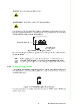
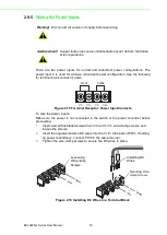
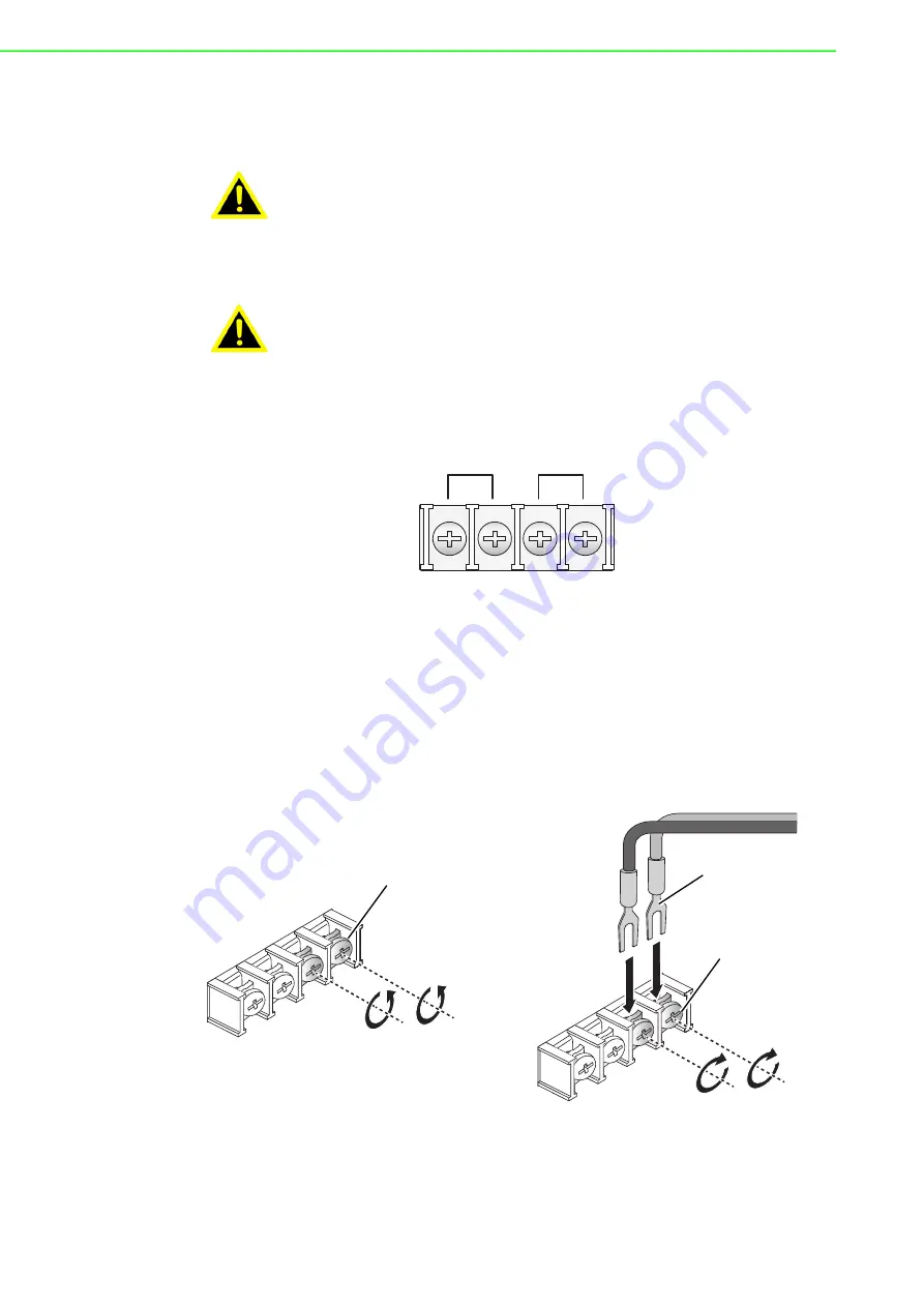
Figure 2.15 Terminal Receptor: Power Input Contacts
To wire the power inputs:
Make sure the power is not connected to the switch or the power converter before
proceeding.
1.
Insert a small flat-bladed screwdriver in the V1+/V1- wire-clamp screws, and
loosen the screws.
2.
Insert the negative/positive DC wires into the V+/V- terminals of PW1. If setting
up power redundancy, connect PW2 in the same manner.
3.
Tighten the wire-clamp screws to secure the DC wires in place.
Figure 2.16 Installing DC Wires in a Terminal Block
Warning!
Disconnect all sources of supply before servicing.
Avertissement!
Couper toutes les sources d'alimentation avant de faire l'entretien
et les réparations.
V1- V1+
V2- V2+
PWR1
PWR2
Loosening
Wire-clamp
Screws
Installing DC
Wires
Securing
Wire-
clamp Screws
Содержание EKI-9226G Series
Страница 1: ...User Manual EKI 9226G Series 6xRJ45 20xSFP Port Full Gigabit L2 Managed Switch ...
Страница 14: ...Chapter 1 1Product Overview ...
Страница 19: ...Chapter 2 2Switch Installation ...
Страница 34: ...Chapter 3 3Configuration Utility ...
Страница 39: ...Chapter 4 4Managing Switch ...
Страница 167: ...Chapter 5 5Troubleshooting ...

