background image

10

EKI-6333AC-1GPO Series User Manual


6.

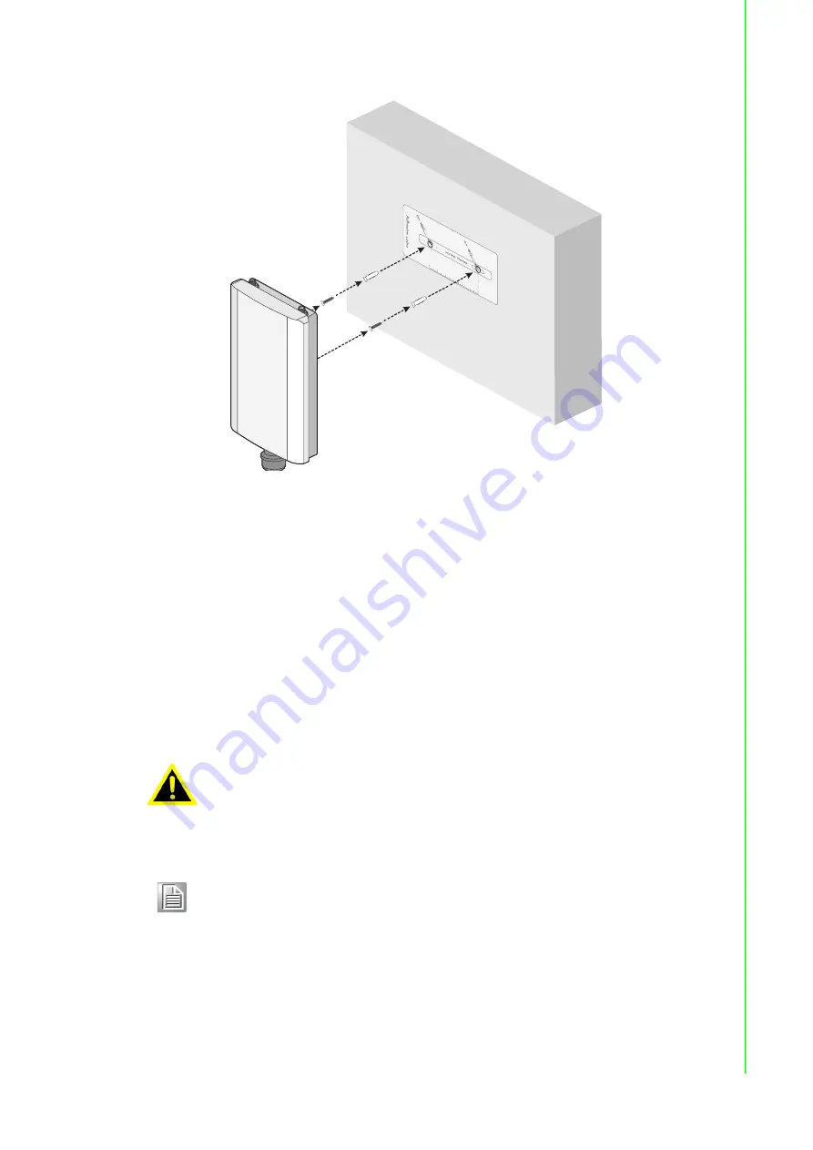
Slide the device down to sit it securely in the mounting screws. 


Figure 2.7 Wall Mount Installation

7.

Connect the cables. See “PoE Injector” on page


11.

8.

Connect the top antennas by turning the antenna in the connectors in a 

clockwise direction.

9.

Repeat for the bottom locations.

2.2.3

Pole Mounting

When mounting an access point, make sure the access point is oriented with the LED 

indicators clearly visible and access to the cable connectors is easily attained.
A pole for installing the device needs to meet the following requirements:
The pole can support up to four times the total weight of the device and mounting 

bracket. 

A mounting kit is required to install the device on a pole. The procedures are as 

follows:

1.

Insert the self-locking tie through the end of the mounting bracket and slide it 

through until it protrudes through the opposite end.

2.

Place the mounting bracket against the pole and position it so the housing cover 

faces down. See the following figure for details.

Warning!

The installation of the access point must comply with local and national 

electrical codes.

Note!

When installing, make sure to allow for enough space to properly install 

the cabling.

Содержание EKI-6333AC-1GPO

Страница 1: ...User Manual EKI 6333AC 1GPO IEEE 802 11 a b g n ac WiFi AP ...

Страница 2: ... installation Advantech assumes no liability under the terms of this warranty as a consequence of such events Because of Advantech s high quality control standards and rigorous testing most of our customers never need to use our repair service If an Advantech product is defective it will be repaired or replaced at no charge during the warranty period For out of warranty repairs you will be billed ...

Страница 3: ...r environmental specifications Test conditions for passing included the equipment being operated within an industrial enclosure In order to protect the product from being damaged by ESD Electrostatic Discharge and EMI leakage we strongly recommend the use of CE compliant industrial enclosure products ...

Страница 4: ...e problem The exact wording of any error messages Warnings Cautions and Notes Document Feedback To assist us in making improvements to this manual we would welcome comments and constructive criticism Please send all such in writing to support advantech com Warning Warnings indicate conditions which if not observed can cause personal injury Caution Cautions are included to help you avoid damaging h...

Страница 5: ...that people cannot step on it Do not place anything over the power cord All cautions and warnings on the equipment should be noted If the equipment is not used for a long time disconnect it from the power source to avoid damage by transient overvoltage Never pour any liquid into an opening This may cause fire or electrical shock Never open the equipment For safety reasons the equipment should be o...

Страница 6: ... period The following guidelines are also recommended Wear a grounded wrist or ankle strap and use gloves to prevent direct contact to the device before servicing the device Avoid nylon gloves or work clothes which tend to build up a charge Always disconnect the power from the device before servicing it Before plugging a cable into any port discharge the voltage stored on the cable by touching the...

Страница 7: ... 3 I O Port Cover 13 2 3 4 Power Connection 13 2 4 Reset Button 13 Chapter 3 Web Interface 14 3 1 Log In 15 3 1 1 Password 15 3 2 Overview 16 3 3 Address Resolution Protocol 17 3 4 Interface Settings 18 3 4 1 LAN 18 3 4 2 WAN 19 3 4 3 Wireless 2 4GHz 21 3 4 4 Wireless 5GHz 38 3 4 5 Wireless Redundant 38 3 5 Network Settings 42 3 5 1 Static Route 42 3 5 2 Forwarding 43 3 5 3 Security 44 3 5 4 IP Qo...

Страница 8: ...ter Mode 26 Figure 3 16 Completed Bridged Repeater Mode Setting 26 Figure 3 17 Wireless 2 4GHz Advanced 27 Figure 3 18 Wireless 2 4GHz Advanced 28 Figure 3 19 Wireless Settings Security 29 Figure 3 20 Security Mode WEP 30 Figure 3 21 Security Mode WPA Personal 31 Figure 3 22 Security Mode WPA WPA2 Enterprise 32 Figure 3 23 Wireless 2 4GHz Multiple SSID 33 Figure 3 24 Wireless 2 4GHz QoS 34 Figure ...

Страница 9: ...gement Syslog 47 Figure 3 49 Management NTP Time 48 Figure 3 50 Management SNMP 49 Figure 3 51 Management Remote Services 50 Figure 3 52 Management Configuration Manager 51 Figure 3 53 Management Firmware Upgrade 51 Figure 3 54 Management Apply Configuration 51 Figure 3 55 Management Apply Configuration 52 Figure 3 56 Management Reboot Device 52 Figure 3 57 Tools Diagnostics 53 ...

Страница 10: ...Chapter 1 1Introduction ...

Страница 11: ...WEP 802 1x WPA WPA2 Personal WPA WPA2 Enterprise Provides Web based configuration Supports dual bands 2 4 5GHz concurrent IP67 Rated waterproof dust proof housing withstands harsh environments 1 3 Specifications Specifications Description Interface I O Port 1 x RJ45 Power Connector RJ45 Physical Enclosure Plastic Mounting Wall pole Dimensions W x H x D 111 2 x 173 6x 30 29 mm 4 37 x 6 83 x 1 19 We...

Страница 12: ... 8 pin RJ45 Power Power Consumption 12 6 W Power Input 802 3af at Compliance Source Software Management Telnet FTP SNMP Web UI SSH Wireless Radio on off WMM Output Power Control Beacon Interval RTS CTS threshold DTIM Interval Operation Modes Access Point mode Client Repeater Configuration Web Browser Protocol ARP ICMP IPv4 IPv6 TCP UDP DHCP Client DHCP Server Telnet DNS SNMP HTTP DMZ VPN Passthrou...

Страница 13: ...Chapter 2 2Getting Started ...

Страница 14: ...EKI 6333AC 1GPO Series User Manual 5 2 1 Hardware 2 1 1 Front View Figure 2 1 Front View No Item Description 1 Housing cover Housing for installation and water proofing cable connection 1 ...

Страница 15: ...o Item Description 1 System LED panel See System Indicators on page 8 5GHz 2 4GHz LAN PWR 1 No Item Description 1 Antenna connector Reverse SMA connector for 2 4 GHz WLAN antenna 2 ETH port LAN RJ45 port WAN LAN connector and passive PoE input port 3 Antenna connector Reverse SMA connector for 5 GHz WLAN antenna 1 2 3 ...

Страница 16: ...2 1 5 Rear View Figure 2 5 Rear View No Item Description 1 Antenna connector Reverse SMA connector for 5 GHz WLAN antenna 2 Antenna connector Reverse SMA connector for 2 4 GHz WLAN antenna 1 2 No Item Description 1 Mounting bracket Bracket to mount device on wall or pole 2 ...

Страница 17: ...nking Wireless port is transmitting or receiving data 2 WLAN 2 4 GHz 3 Ethernet LAN Port Green blinking Ethernet port is transmitting or receiving data Off Cable connection lose no connection 4 PWR Power connected Off Power failure On Booting status Amber Boot complete Amber blinking Boot state in progress firmware update 1 5GHz 2 4GHz LAN PWR 2 3 4 ...

Страница 18: ...is required to install the device on a wall The procedures are as follows 1 Place a sheet of paper or similar material over the mounting bracket to mark the mounting holes on the paper 2 Place the diagram of the mounting holes on the installation location and mark the positions of the mounting holes with a marker 3 Remove the diagram from the location and use a drill bit to drill holes in the mark...

Страница 19: ...ole for installing the device needs to meet the following requirements The pole can support up to four times the total weight of the device and mounting bracket A mounting kit is required to install the device on a pole The procedures are as follows 1 Insert the self locking tie through the end of the mounting bracket and slide it through until it protrudes through the opposite end 2 Place the mou...

Страница 20: ...ng the antenna in the connectors in a clockwise direction 8 Repeat for the bottom locations 2 3 Cable Connections 2 3 1 PoE Injector The device is designed to connect to an 802 3at af PoE injector or switch not included to allow access to power and data through a single Ethernet cable supplying both to an access point 1 Locate the bottom of the device The housing covers are attached 2 Unscrew the ...

Страница 21: ...ted when installed correctly 2 3 2 Network Connection For RJ45 connectors data quality twisted pair cabling rated CAT5 or better is recommended The connector bodies on the RJ45 Ethernet ports are metallic and connected to the GND terminal For best performance use shielded cabling Shielded cabling may be used to provide further protection Figure 2 10 Ethernet Plug Connector Pin Position Maximum cab...

Страница 22: ...ect modules or cabling unless the power is first switched off The device only supports the voltage outlined in the type plate Do not use any other power components except those specifically designated for the device Caution Disconnect the power cord before installation or cable wiring Warning Power down and disconnect the power cord before servicing or wiring the device Caution Do not disconnect m...

Страница 23: ...Chapter 3 3Web Interface ...

Страница 24: ...ent interface You can change the default password after you have successfully logged in 4 Click Login to enter the management interface Figure 3 1 Login Screen 3 1 1 Password The Management page allows you to configure the WiFi AP login details 1 Log in to the user interface menu see Log In on page 15 2 Navigate to Home Management Password Manager The Password Manager page displays 3 The profile t...

Страница 25: ... of the device Local Hostname Display the current local hostname of the device System Time Displays the current date of the device System Up Time Displays the time since the last device reboot Model Name Displays the model name of the device LAN Interface LAN Status Displays the current IP and MAC settings TX packets bytes and RX packets bytes Wireless 2 4GHz Displays the current settings for the ...

Страница 26: ...SID name BSSID encryption type channel TX power and assigned region country WAN Interface Local IP Address Displays the type of WAN physical interface setup Disabled default static DHCP DHCP Leases Displays the defined list of DHCP leases that the DHCP server has assigned Defines hostname IPv4 Address MAC Address and Lease Time Remaining System Status Memory Utilization Displays the total memory u...

Страница 27: ...s Setting mode Static or DHCP IP Address Enter a value to specify the IP address of the interface The default is 192 168 1 1 Subnet Mask Enter a value to specify the IP subnet mask for the interface The default is 255 255 255 0 DHCP Server DHCP Server Click the radio button to enabled or disabled the DHCP server function Start IP Address Enter starting a IP address for the IP assignment Pool Count...

Страница 28: ...onfiguration settings appear Figure 3 8 Interface WAN Network Mode Static The following table describes the items in the previous figure Note All new configurations will take effect after rebooting To reboot the device click Management Apply Configuration Apply and Reboot Item Description Network Mode Click the drop down menu to select the mode type Disable default Static DHCP WAN Interface Click ...

Страница 29: ... address given by your service provider Static DNS 2 Enter the secondary WAN DNS IP address given by your service provider Submit Click Submit to save the values and update the screen Item Description Network Mode Click the drop down menu to select the mode type Disable default Static DHCP WAN Interface Click the radio button to select the specific interface to configure Submit Click Submit to sav...

Страница 30: ...oint Mode To access this page click Wireless 2 4GHz Basic and select Access Point in Operation Mode Figure 3 11 Wireless 2 4GHz Basic Access Point The following table describes the items in the previous figure Note The maximum number of concurrent clients on the AP to prevent affecting user experience is 20 Item Description Wireless Network Enable Wireless Interface Click to enable or disable the ...

Страница 31: ...e transmission signal stream single or dual stream Operation frequency Country Code Click the drop down menu to select the country code to specify different selectable channels Available options US Germany France China Japan etc Some specific channels and or operational frequency bands are country dependent Channel Selection Click the drop down menu to select Auto default or Manual The Auto select...

Страница 32: ...ifiers BSSID for the device Scan AP Click to rescan the selected SSID Management Frame Protection Click the radio button to enable disable or set the function to optional The wireless feature increases the security of the management frames standard IEEE 802 11W 2009 Tx Rx Click to select the transmission signal stream single or dual stream Operation frequency Country Code Click the drop down menu ...

Страница 33: ...idged Repeater WDS Click the radio button to enable or disable the Wireless Distribution System WDS to allow you to link the Access Points wirelessly Main SSID Enter the source SSID network to be repeated BSSID Displays the basic service set identifiers BSSID for the device Scan AP Click to rescan the selected SSID Extender SSID Enter the SSID name to use for transmitting the Main SSID signal The ...

Страница 34: ...China and Japan Some specific channels and or operational frequency bands are country dependent Band Click the drop down menu to select the band channel Band Channel bandwidth Click the drop down menu to select the band and channel bandwidth 11b g Non HT Legacy 11n HT20 11n HT40 or 11ac VHT 80 Channel Frequency Click the drop down menu to select a wireless channel frequency AutoSelect Channel 1 2 ...

Страница 35: ...ings Figure 3 15 Enabling Bridged Repeater Mode The following figure depicts a completed Bridged Repeater configuration between an AP device Main SSID a repeater device and a client device extender SSID Figure 3 16 Completed Bridged Repeater Mode Setting 3 4 3 2 Advanced Access Point and Bridge Repeater Modes To view the Advanced menu the Basic Operation Mode must be designated to Access Point or ...

Страница 36: ...abled HT LDPC Enable to advertise Low density Parity Check LDPC support By enabling HT LDPC the function improves data transmission over channels with a high degree of background noise default enabled Station Inactivity Time Enter the value in seconds 30 to 86400 default 300 to define the period of traffic inactivity for a client before the AP removes it Advanced Wireless Setting RTS Threshold Ent...

Страница 37: ...forced With Roam disabled a delay is enforced before clients are allowed to move between SSID RSSI threshold Enter the value to designate the transmit power setting range 1 75 default 65 A higher value causes the access points to operate at higher transmit power rates A lower value results in lowered transmit power rates RSSI hysterisis Enter the value to indicate how much greater the signal stren...

Страница 38: ...ng packets in a Ping interval Ping Loss Counter Enter the variable to define the number of failed ping count s that the device can send continuously If the value is exceeded the Action is initiated MAC Clone Click to enable or disable the MAC clone function Advanced Wireless Setting Transmission Power Use the scroll bar to set the transmission power from Low to High Short Guard Interval Click the ...

Страница 39: ...key is required and only sharing the same key with other wireless devices can the communication be established Wire Equivalence Protection WEP Default Key Index Click the drop down menu to select one of the four defined key indexes as defined by the WEP Key fields in the following WEP Key 1 Enter up to four WEP keys Enter a string of characters dependent on the key type ASCII Upper and lower case ...

Страница 40: ... Personal WPA Version Click the drop down menu to designate the specific authentication type Settings WPA1 WPA2 WPA1 WPA2 WPA Cipher Click the drop down menu to select the encryption type Settings TKIP AES TKIP AES Pass Phrase Enter the a unique password to define the passphrase for authentication access Click Unmask to view the password entry 802 11r 802 11r Fast Transition Roaming Click to enabl...

Страница 41: ...n the same management VLAN 802 11r the same value must correspond across the same management VLAN Reassociation Deadline Enter a timeout value in seconds The range is 1000 to 65535 default 1 024 ms Submit Click Submit to save the values and update the screen Item Description Security Policy Security Mode Click the drop down menu to select the encryption when communication Available options None WE...

Страница 42: ...and update the screen Item Description Item Description Add Click Add after completing the SSID information to create the wireless network and list it in the menu Add SSID State Click the radio button to designate the state enabled disabled of the defined SSID SSID Enter the text string identifying the name of the SSID SSID Broadcast Click the drop down menu to enable visible or disable not broadc...

Страница 43: ...ailable options None WPA Personal and WPA WPA2 Enterprise If data encryption is enabled the key is required and only sharing the same key with other wireless devices can the communication be established Submit Click Submit to save the values and update the screen Item Description Item Description Interface Name Click the drop down menu to select an interface from the list of already created wirele...

Страница 44: ...quency Display the current channel frequency of the device BSSID Display the MAC address of the device Station List Station BSSID Displays the basic service set identifier BSSID access point unique MAC address Signal level Displays the power level measure in decibel milliwatts of the listed BSSID Connected time Displays the total uptime period Tx Rx rate Displays the transmit Tx to receive Rx rate...

Страница 45: ...y Item Description SSID Click the drop down menu to select the SSID from the list of already created wireless networks Access Control Method Click the drop down menu to set the access control method Disable Deny or Allow In the Deny or Allow menu enter the MAC address of the target device support for up to 32 target devices Submit Click Submit to save the values and update the screen Item Descript...

Страница 46: ...n VLAN ID Enter a variable 3 to 127 to identify the VLAN entry Wireless SSID Click the drop down menu to select an SSID entry to configure to the VLAN entry Delete Click Delete to remove the VLAN entry from the list Add Click Add after completing the SSID information to create the wireless network and list it in the menu Submit Click Submit to save the values and update the screen Wireless Client ...

Страница 47: ...le is disconnect and the slave role is activated Figure 3 32 Wireless Redundancy Enabled The Role Exchange Setting menu follows as seen in the following figure Item Description Download Click Download to download the log file Auto Scroll Click the option to allow for auto scrolling when the log entries has extended below the page line Item Description Redundant Status Master Displays the interface...

Страница 48: ...tting range 1 75 default 65 A higher value causes the access points to operate at higher transmit power rates A lower value results in lowered transmit power rates RSSI Differ If the slave scans and finds that the signal strength is better than the originally connected AP if it is greater than the set value it will switch to connect to the AP range 1 30 default 10 Interval Enter the value in ms to...

Страница 49: ...20 10000 default 100 Failures Number Enter the value to designate the failure threshold range 1 10 default 3 Item Description 2 4G 5G 2 4G 5G transmit blocked Ethernet Ether Ethernet G Ethernet 2 4G 5G 2 4G 5G Ethernet Ether Ethernet G Ethernet RSSI value defined threshold RSSI value defined threshold NB PC NB PC NB PC NB PC 2 4G 5G 2 4G 5G Ethernet Ether NB PC G NB PC NB PC NB PC Ethernet NB N PC...

Страница 50: ...I threshold RSSI Differ The set value to determine the threshold for selecting an AP connection based on signal strength Above Threshold Scan Interval The interval time during an active RSSI RSSI threshold scan background scan The default is 120 seconds Below Threshold Scan Interval The interval time during a local RSSI RSSI Threshold scan The default is 15 seconds Submit Click to save the configu...

Страница 51: ...e The following table describes the items in the previous figure 2 4G 5G 2 4G 5G Ethernet Ether NB PC G NB PC Ethernet Item Description Target IP Address Enter an IP address static route for this static route Netmask Enter a netmask setting static route for this static route Gateway Enter a gateway setting static route for this static route Interface Enter an interface for this static route option...

Страница 52: ...me Enter a text string to identify the port forwarding entry Start Port Enter the value of the starting port for this entry End Port Enter the value of the ending port for this entry Local IP Enter the IP address defining the static address of the local IP Local Port Enter the value defining the local port Protocol Click the drop down menu to select the protocol setting options TCP UDP Both Delete...

Страница 53: ... Filtering Destination Port Filtering Port Forwarding as well as DMZ Source IP Filtering The source IP filtering gives users the ability to restrict certain types of data packets from users local network to Internet through the device Use of such filters can be helpful in securing or restricting users local network To access this page click Networking Security Filter Figure 3 43 Networking Securit...

Страница 54: ...col Click the drop down menu to select the protocol type for the entry TCP UDP ICMP Source port Enter the port number of the sender IP address Destination port Enter the port number of the destination IP address Delete Click Delete to remove the entry from the Filter policy Add Click Add to include the entry in the Filter policy Submit Click Submit to save the values and update the policy Item Des...

Страница 55: ...s Enter the IP address of the rule entry Download rate Enter a value to specify the maximum download bandwidth Upload rate Enter a value to specify the maximum upload rate Unit Click the drop down menu to specify the unit of the bandwidth rate Kbit s Mbit s Delete Click Delete to remove the entry from the rule Add Click Add to include the entry in the Filter policy Submit Click Submit to save the ...

Страница 56: ... Users can enable the syslogd function to record historical events or messages locally or on a remote syslog server To access this page click Management Syslog Figure 3 48 Management Syslog Item Description Password Enter the text string to define a password for the listed username entry Confirm Password Re type the text string as identified in the password field to confirm the entry Submit Click ...

Страница 57: ...ng logging information Submit Click Submit to save the values and update the screen Download Click Download to download the log file Auto Scroll Click the option to allow for auto scrolling when the log entries has extended below the page line Item Description System Time Displays the current system time settings Manual Time To enable manual configuration NTP Service option must first be disabled ...

Страница 58: ...e contact entry Location Enter the text string describing the region location of the contact entry Description Enter a descriptive remark to better identify the contact entry SNMP Daemon Settings Version Click the drop down menu to select the version of the daemon Server Port Enter the port to access on the specified server Read Community Enter the setting to define the level of read access for th...

Страница 59: ...s to HTTPS Click the drop down menu to enable or disable the function By default the function is disabled When enabled a NAT setting and Open Ports can be setup to direct connection requests to an internal server HTTPS port Enter the port to forward HTTPS traffic default 443 HTTP port Enter the port to forward HTTP traffic default 80 SSH SSH Click the radio button to enable or disable access to SS...

Страница 60: ...re 3 53 Management Firmware Upgrade The following table describes the items in the previous figure 3 6 8 Reset System To access this page click Management Apply Configuration Figure 3 54 Management Apply Configuration Item Description Backup Backup Click Backup to export the device settings Restore Upload Archive Click Upload Archive to select a previously saved configuration file Item Description...

Страница 61: ...ce Figure 3 56 Management Reboot Device The following table describes the items in the previous figure Item Description Reset Click Reset the device any changes to settings will be lost unless the Apply Configuration function is executed prior to resetting Item Description Apply and Reboot Click Apply and Reboot to save the new configuration settings and reboot the device to permanently save the n...

Страница 62: ...ods Each label must be between 1 and 63 characters long maximum of 64 characters Ping Click Ping to display ping result for the IP address IP Address or Hostname Enter the IP address or host name of the station to ping The initial value is blank The IP Address or host name you enter is not retained across a power cycle Host names are composed of series of labels concatenated with periods Each labe...

Страница 63: ...ations are subject to change without notice No part of this publication may be reproduced in any form or by any means electronic photocopying recording or otherwise without prior written permission of the publisher All brand and product names are trademarks or registered trademarks of their respective companies Advantech Co Ltd 2021 ...

Отзывы: