background image


Electrical installation, cable connection, cable cover 


108 / 140 


DLT-V72 Operating Instructions V2.50 Preliminary 

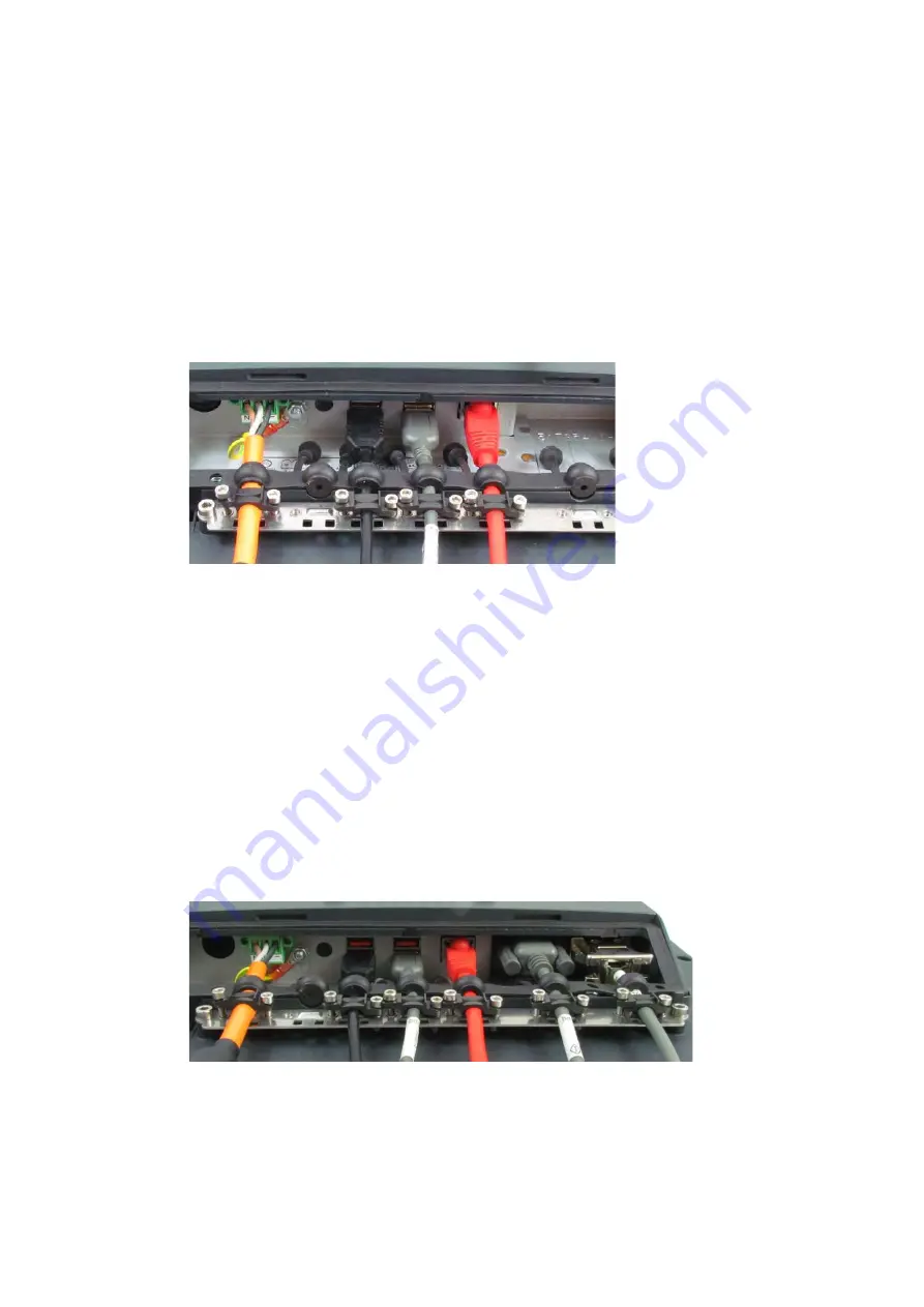
12.4.2.  Ethernet cable 


Plug the Ethernet cable into the associated port. 


Fold open the round cable passage in the rubber seal. 


Insert the Ethernet cable. 


Secure Ethernet cable to the strain relief rail with cable clips and screws. 


ATTENTION

 Tighten the mounting screws sufficiently but on no account pinch or crush the cable. 

If you do, the cables may break or the cable insulation may get damaged. 


Fig. 12.6: Ethernet cable on the connector panel; secured to the strain relief rail 


12.4.3.  COM cable 


Plug the required COM cable into the associated port. 


Fold open the respective round cable passage in the rubber seal. 


Insert the COM cable. 


Secure the COM cable to the strain relief rail with cable clips and screws. 


ATTENTION

 Tighten the mounting screws sufficiently but on no account pinch or crush the cable. 

If you do, the cables may break or the cable insulation may get damaged. 


Fig. 12.7: COM cable on the connector panel; secured to the strain relief rail 


Содержание DLT-V72 Series

Страница 1: ...DLT V72 Industrial Computer Operating Instructions V2 50 EN Preliminary ...

Страница 2: ...ment Advantech Co Ltd is not responsible for the accessibility of the websites and for the content of external links contained in this document The content and accessibility of the linked websites are the sole responsibility of their operators Acknowledgements The software and hardware designations as well as the brand names used in this documentation are in most cases also registered trademarks a...

Страница 3: ...side DLT V7210 K KD 41 7 3 4 Front side DLT V7212 P 42 7 3 5 Integrated keyboard 43 7 4 Operating states 44 7 5 Software keyboard optional 45 7 6 Operating the DLT V72 with UPS 45 8 GENERAL DEVICE CONFIGURATION 46 8 1 Operating systems available optional 46 8 2 MS Windows optional 46 8 2 1 General 46 8 2 2 Configuring the front keys automatic shutdown etc 46 8 2 3 WES 7 and Win 7 Prof USB icon in ...

Страница 4: ...4 1 2 DC Power supply cable 117 15 OPTIONAL EQUIPMENT 118 15 1 Integrated UPS optional 118 15 1 1 Battery pack specifications 119 15 1 2 Charging the battery pack 120 15 1 3 Replacing the battery pack 120 15 2 Screen defroster optional 122 15 3 Keyboards and keyboard mounts optional 123 15 4 Scanner and scanner bracket optional 124 15 5 Touch stylus 125 15 6 USB recovery stick optional 125 15 7 Pr...

Страница 5: ...sites DLoG Config manual Advantech Linux manual etc Description of software for the DLT V72 Skilled personnel Mounting instructions for accessories Description of mounting steps Skilled personnel Printed enclosed with the respective accessories Pay attention to these manuals because they help avoid hazards reduce repair costs and downtimes and increase the reliability and service life of the DLT V...

Страница 6: ... models of the DLT V72 series DLT V7210 P PCT DLT V7210 R Resistive Touch DLT V7210 D Defroster DLT V7212 P PCT DLT V7212 R Resistive Touch DLT V7212 D Defroster DLT V7210 K Integrated Keyboard DLT V7210 KD Integrated Keyboard and Defroster DLT V7212 P P CAP Differences with regard to operation functionality etc are clearly indicated in the manual ...

Страница 7: ...not observed WARNING means that death or severe bodily injury can occur if this information is not observed CAUTION means that slight bodily injury can occur if this information is not observed Property damage Information about Property damage is shown as follows NOTICE Property damage Information about possible Property damage Tips for handling product and operating instructions Tips for handling...

Страница 8: ...r for technical support Please have the following information ready Product name Serial number Description of your peripheral attachments Description of your software operating system application software etc The exact wording of any error messages A complete description of the problem Find the contact data of our Global Advantech Service Centers on our website http erma advantech com ...

Страница 9: ...ns and the compliance with the approved environmental conditions and specifications for the device The DLT V72 Industrial Computers are not approved for use in EX zones potential explosion hazard are not approved for use on ships are not approved for use on railed vehicles are not approved for use in life support systems or critical safety systems where system malfunction can lead to the direct or...

Страница 10: ... device is installed incorrectly or configured improperly operated by untrained or uninstructed personnel improperly operated and maintained not used as intended The owner operator commitments with regards to safety accident prevention regulations occupational safety are to be followed 3 3 Device identification name plate The name plate on the rear side of the DLT V72 must be legible at all times ...

Страница 11: ...edges and cause cutting injuries Always hold the DLT V72 by the housing with both hands Never use the antenna as a handle It can break due to the weight involved Do not hold the DLT V72 by the strain relief rail Use the assistance of a second person for installation work 4 3 Storage 4 3 1 DLT V72 without UPS Observe the permissible storage temperature range in the manual section 5 2 Environmental ...

Страница 12: ...mes or heaters Do not allow it to come into contact with fire Have suitable fire extinguishers ready foam or powder in accordance with safety regulations Prevent deep discharge NOTICE Physical damage Deep discharge of the battery pack due to incorrect storage Storing the lithium ion batteries incorrectly will cause them to discharge completely deep discharge and thus damage them irreparably Store ...

Страница 13: ...T V7210 KD Approx 3 7 kg DLT V7212 P Approx 3 7 kg Battery pack Approx 0 15 kg Material Rugged aluminum cast housing ESD safe Display DLT V7210 10 4 XGA color TFT with 1024 x 768 resolution and 400 cd m brightness DLT V7212 12 1 XGA color TFT with 1024 x 768 resolution and 500 cd m brightness DLT V7210 K DLT V7210 KD 10 1 widescreen WXGA color TFT display with 1280 x 800 resolution and 500 cd m br...

Страница 14: ...lcohols Dilute Acids Dilute Alkalis Esters Hydrocarbons Ketones Household Cleaning agents according to DIN 42 115 Projected capacitive touchscreen PCT Type Projected capacitive touchscreen Construction Glass film Surface Hardness JIS K 5400 10 H at 750 g Chemical AR coated glass DLT V7210P and DLT V7212P gloss value 85 at 60 DLT V7210K gloss value 70 at 60 according to ISO 2813 7668 ASTM D 523 D 2...

Страница 15: ... UPS Operating temperature 30 to 50 C Specification according to EN 60068 2 1 2 Storage temperature 30 to 65 C Specification according to EN 60068 2 1 2 Relative humidity 10 to 90 at 40 C relative humidity Noncondensing Specification according to EN 60068 2 3 Mechanical vibration and shock resistance Class 5M3 according to EN 60721 3 5 US Highway Truck according to MIL STD 810F IP protection class...

Страница 16: ...Technical data Device 16 140 DLT V72 Operating Instructions V2 50 Preliminary 5 3 Device dimensions 5 3 1 DLT V7210 P R D Dimensions without add ons in mm Fig 5 1 Dimensions DLT V7210 P R D ...

Страница 17: ...Technical data Device DLT V72 Operating Instructions V2 50 Preliminary 17 140 5 3 2 DLT V7212 P R D Dimensions without add ons in mm Fig 5 2 Dimensions DLT V7212 P R D ...

Страница 18: ...Technical data Device 18 140 DLT V72 Operating Instructions V2 50 Preliminary 5 3 3 DLT V7210 K KD Dimensions without add ons in mm Fig 5 3 Dimensions DLT V7210 K KD ...

Страница 19: ...Technical data Device DLT V72 Operating Instructions V2 50 Preliminary 19 140 5 3 4 DLT V7212 P Dimensions without add ons in mm Fig 5 4 Dimensions DLT V7212 P ...

Страница 20: ...sed to attach VESA compatible mountings to mount the DLT V72 at the deployment location ATTENTION Physical damage Only use mountings and mounting materials that have been tested and approved for the respective DLT V72 Otherwise any warranty for this device will be void 5 4 1 DLT V7210 P R D Dimensions without add ons in mm Depth of thread M6 x 6mm Fig 5 5 Position VESA drill holes DLT V7210 P R D ...

Страница 21: ...hnical data Device DLT V72 Operating Instructions V2 50 Preliminary 21 140 5 4 2 DLT V7212 P R D Dimensions without add ons in mm Depth of thread M6 x 6mm Fig 5 6 Position VESA drill holes DLT V7212 P R D ...

Страница 22: ...chnical data Device 22 140 DLT V72 Operating Instructions V2 50 Preliminary 5 4 3 DLT V7210 K KD Dimensions without add ons in mm Depth of thread M6 x 6mm Fig 5 7 Position VESA drill holes DLT V7210 K KD ...

Страница 23: ...Technical data Device DLT V72 Operating Instructions V2 50 Preliminary 23 140 5 4 4 DLT V7212 P Dimensions without add ons in mm Depth of thread M6 x 6mm Fig 5 8 Position VESA drill holes DLT V7212 P ...

Страница 24: ...ows Read off the FCCID on the device name plate label and compare with the technical data on the following pages Open the Device Manager to determine the name of the radio card for example The radio equipment variants for Wi Fi WWAN GNSS and Bluetooth are available as options and are not included in the standard scope of delivery of the DLT V72 6 2 Radio cards optional WARNING Only the manufacture...

Страница 25: ...A 261ACBT Band 1 WLAN 2 4 GHz Frequency range 2400 to 2483 5 MHz Frequency band ETSI Europe 2 4 GHz to 2 4835 GHz Channels available 1 to 13 WIFI 0 to 78 BT Supported standards Wi Fi IEEE802 11 a b g n ac and Bluetooth both supported via a single antenna Maximum TX power 20 dBm WIFI 10 dBm BT Band 2 WLAN 5 GHz Frequency range 5150 to 5875 MHz Frequency band ETSI Europe 5 15 GHz to 5 35 GHz 5 47 GH...

Страница 26: ...echnology WWAN 2G 3G 4G cellular bands and GNSS FCCID FCC ID XMR201605EC25A valid for the EC25 A variant Maximum transmitting power Class 3 23dBm 2dB for LTE FDD Class 3 23dBm 2dB for LTE TDD Class 3 24dBm 1 3dB for TD SCDMA Class 3 24dBm 1 3dB for WCDMA Class E2 27dBm 3dB for EDGE 850 900MHz Class E2 26dBm 3 4dB for EDGE 1800 1900MHz Class 4 33dBm 2dB for GSM 850 900MHz Class 1 30dBm 2dB for GSM ...

Страница 27: ...al data Application Wi Fi a b g n ac Dual Band with MRC Bluetooth integrated via Radio card Wi Fi frequency range Band 1 2400 to 2483 5 MHz Band 2 5150 to 5850 MHz Bluetooth features See section 6 4 1 Bluetooth Number of antennas 2 Available color Red Type PIFA antenna Antenna gain Max 3 44 dBi Band 1 2 85 dBi Band 2 Impedance 50 Ω Polarization Vertical horizontal Maximum transmitting power 100 mW...

Страница 28: ...B8 GSM 900 1800 WWAN frequency bands with EC25 A FDD LTE B2 B4 B12 WCDMA B2 B4 B5 Bluetooth features See section 6 4 1 Bluetooth Number of antennas 4 Available color Red Type PIFA antenna Wi Fi Dipole antenna WWAN Antenna gain Wi Fi Max 2 8 dBi 2 4G Band 2 8 dBi 5G Band WWAN Max 3 5 dBi Impedance 50 Ω Polarization Vertical horizontal Maximum transmitting power Wi Fi 22 dBm WWAN Class 3 23dBm 2dB f...

Страница 29: ...r detached mounting e g on the roof of the forklift Wi Fi frequency range Band 1 2400 to 2485 MHz Band 2 5150 to 5875 MHz Number of antennas 1 Type Dipole antenna Antenna gain Band 1 Max 3 5 dBi Band 2 Max 2 9 dBi Impedance 50 Ω Polarization Vertical horizontal Dimensions Ø 86 x 43 mm Ø 3 39 x 1 69 Weight 0 3 kg 0 66 lbs Connector labeling N type or TNC N Jack female bottom RSMA plug for RSMA sock...

Страница 30: ...in Max 3 02 dBi Impedance 50 Ω Polarization Vertical Dimensions Height 79 45 mm Diameter 42 mm Cable length 3 m IP protection IP67 and IP69K Max transmitting power of antenna Class 3 23dBm 2dB for LTE FDD Class 3 23dBm 2dB for LTE TDD Class 3 24dBm 1 3dB for TD SCDMA Class 3 24dBm 1 3dB for WCDMA Class E2 27dBm 3dB for EDGE 850 900MHz Class E2 26dBm 3 4dB for EDGE 1800 1900MHz Class 4 33dBm 2dB fo...

Страница 31: ... V3 0 HS V2 1 EDR Transmission rate 1 Mbps 2 Mbps up to 3 Mbps 6 4 2 Micro Bluetooth adapter USB stick The optional micro Bluetooth adapter permits the Wi Fi connection between the DLT V72 and Bluetooth devices If the Bluetooth option was ordered this adapter is already integrated into the Service USB interface under the antenna Technical data Type USB adapter Bluetooth 2 0 Transmission rate EDR t...

Страница 32: ...osition data of the Global Positioning System GPS and communicates with the DLT V72 via USB interface We recommend using only a GPS receiver approved by Advantech Fig 6 8 External GPS receiver optional Installation The installation CD supplied with the GPS receiver includes installation files and a multi lingual manual Please read the additional information in the manual about the GPS receiver Fig...

Страница 33: ... on a vehicle and connected with the ignition signal What are the automatic shutdown settings that were defined in the DLoG Config configuration program 7 1 1 Switch on Switch the DLT V72 on as follows depending on the configuration Press the Power button Or By applying the supply voltage Or Through the ignition signal of the vehicle depends on automatic shutdown settings Fig 7 1 Power button of t...

Страница 34: ... If the DLT V72 has been configured to also start without Power button and ignition in the DLoG Config program this setting will need to be changed first Otherwise the DLT V72 will restart after a short pause as long as there is available battery capacity Shut down the DLT V72 via the operating system function Disconnect from the power supply Open the battery cover unplug the battery pack Time bet...

Страница 35: ...h or hard objects e g ball point pens writing implements tools of any kind e g screwdrivers Make sure that no adhesives get on the surface of the touchscreen Ensure that the screen surface is not influenced by high voltages or static electricity Do not use excessive force when touching touchscreens do not hit or press hard If the device with the touchscreen is placed down Place a clean soft cloth ...

Страница 36: ...Operation DLT V72 Operating Instructions V2 50 Preliminary 39 140 7 3 Operation elements 7 3 1 Rear side DLT V72 all device models ...

Страница 37: ...ctions V2 50 Preliminary 7 3 2 Front side DLT V7210 P R D and DLT V7212 P R D Background lightning of the display on off NOTE The DLT V7210K will continue to react to keyboard mouse and touchscreen inputs even if the backlight is switched off ...

Страница 38: ...structions V2 50 Preliminary 41 140 7 3 3 Front side DLT V7210 K KD Background lightning of the display on off NOTE The DLT V7210K will continue to react to keyboard mouse and touchscreen inputs even if the backlight is switched off ...

Страница 39: ...Operation 42 140 DLT V72 Operating Instructions V2 50 Preliminary 7 3 4 Front side DLT V7212 P ...

Страница 40: ...board of the DLT V7210 K and KD models is available in three languages German English and French Example English version QWERTY Description of specific keys Key Function Shift key Caps Lock permanent switch to uppercase letters Activate the FN key on the left of the device See the explanation there Windows key ...

Страница 41: ...he Power key after switch off no voltage supply OFF FLASHING Temperature sensor faulty FLASHING OFF DLT V72 is in standby mode S3 OFF ON Computer will only start if the temperature in the device is in the range between 30 and 59 C again ON OFF Computer start up normal operational state shutdown delay time ON ON Screen defroster active ON FLASHING Ambient temperature lies outside of the permitted r...

Страница 42: ...ion department For subsequent installation an installation program is available The manual for the DLoG software keyboard is available on our websites 7 6 Operating the DLT V72 with UPS WARNING Personal injury due to short circuit fire chemical burns toxic substances DLT V72 devices with integrated UPS contain lithium ion battery packs These can ignite if handled or stored improperly risk of fire ...

Страница 43: ... Debian based Linux IGEL Linux 8 2 MS Windows optional 8 2 1 General If a DLT V72 with preinstalled operating system is placed into operation this operating system will be loaded after the BIOS system messages System specific device drivers e g for graphics sound network touchscreen are already installed In DLT V72 units with a pre installed operating system the system is located on the C partitio...

Страница 44: ...r all MS Windows operating systems ATTENTION Physical damage All DLT V72 devices with MS Windows have had the power options set at the factory so that the optimal duration of the battery pack can be achieved The power saving plan is set to power options DLoG Do not modify or deactivate the power options DLoG Under certain circumstances and configurations a modification may cause the battery pack o...

Страница 45: ...ck for Updates Delete the entry manually from the Windows registry Restart the computer Search for updates 8 3 Android The configuration of the DLT V72 with Linux with regard to radio networks touchscreen calibration etc is described in the Advantech Android Manual Please contact our Technical Customer Support if required 8 4 Linux optional The configuration of the DLT V72 with Linux with regard t...

Страница 46: ...ition input are constantly monitored If the DLT V72 s internal temperature reaches a critical level a controlled shutdown of the operating system is carried out The computer will remain switched off until the temperature is once again within the permitted range If the ignition input is grounded or isolated during normal operation of the DLT V72 the device will switch to a delayed shut off state Th...

Страница 47: ...or of DLT V72 with MS Windows Configuring the automatic shutdown is described in the DLoG Config Manual The DLoG Config Manual is available on our websites Configure automatic shutdown behavior of DLT V72 with Android Configuring the automatic shutdown is described in the Advantech Android Manual Please contact our Technical Customer Support if required Configure automatic shutdown behavior of DLT...

Страница 48: ...omply with the regulations for the respective country where the device is deployed Observe all applicable regulations for your deployment location country with regard to operating channels radio frequencies and the maximum permissible transmitting power Responsibility for this lies with the company operating the DLT V72 The regulatory authorities in the relevant country can provide information on ...

Страница 49: ... configuration of the DLT V72 with Linux is described in the Advantech Linux Manual Please contact our Technical Customer Support if required 9 3 Preparation work at the factory The following preparations have already been carried out at the factory for the optional radio functionality of the DLT V72 4 The radio card and the corresponding drivers are installed 5 A default profile with basic settin...

Страница 50: ...N Windows Laird Connection Manager LCM Password SUMMIT upper case mandatory Wireless Zero Configuration abbreviation WZC No password required SPARKLAN WPEQ 261 ACN BT Qualcomm Atheros QCA61x4A Wireless Network Adapter Windows Advantech Wi Fi Client Manager IGX Tool Password gold Wireless Zero Configuration abbreviation WZC No password required Linux Linux Configuration Utility 9 5 Windows Zero Con...

Страница 51: ...f the image has been reinstalled the DLT V72 must be set up again using the IGX Wi Fi driver Two drivers are available 10 Driver for Win7Pro WinEmbStd7 11 Driver for Win8 1IndPro Win10IoTEnt 9 6 3 Requirements The currently available IGX drivers can be downloaded from the following website www advantech service iot eu Downloads Service Drivers Link to FTP Advantech DLoG_Products Additional Drivers...

Страница 52: ...32 or 64 bit is installed on the DLT V72 the system overview can be used for testing Fig 9 1 System overview in Control Panel For 32 bit systems Open the subfolder Win7_X86 Run Setup exe to start the installation For 64 bit systems Open the subfolder Win7_X64 Run Setup exe to start the installation NOTE Setup exe in the main folder is not supported in WinEmbStd7 ...

Страница 53: ...V2 50 Preliminary Example screenshot for 64 bit system subfolder Win7_X64 Fig 9 2 Setup exe for 64 bit operating system in the subfolder Win7_X64 NOTE The remaining installation workflow is covered in the next chapter and is identical in all operating systems ...

Страница 54: ...start the installation NOTE The following installation example shows the Win8 1 10 driver For Windows7 installation please use the corresponding Win7 driver Fig 9 3 Setup exe for 64 bit operating systems Win8 1 10 If the C executables runtimes required for the installation are missing on the operating system these must be set up before running the Wi Fi driver installation Respond to the relevant ...

Страница 55: ...he following window is displayed that starts the actual driver installation process Fig 9 4 IGX driver installation Welcome dialog Continue the installation with Next Fig 9 5 IGX driver installation user and company name In this dialog enter a username and a company name and confirm with Next ...

Страница 56: ...ns V2 50 Preliminary 59 140 Fig 9 6 IGX driver installation All program features Leave the Complete option enabled Continue the installation with Next Fig 9 7 IGX driver installation starts Continue the installation of the required files with Install ...

Страница 57: ...curity Ensure that the Always trust software from option has been selected Continue the driver installation with Install Fig 9 9 IGX driver installation Exit with Finish Exit the driver installation with Finish NOTE It is recommended to run the required system re start directly following installation Select Yes I want to restart my computer now Press the Finish button ...

Страница 58: ...Wi Fi configuration DLT V72 Operating Instructions V2 50 Preliminary 61 140 The system re start is carried out Fig 9 10 IGX driver installation Perform computer re start ...

Страница 59: ...0 Preliminary 9 6 6 Start Wi Fi Client Manager Login Launch the Wi Fi Client Manager by double clicking the Launch WCU icon Fig 9 11 WCU icon on the desktop You must login as WCU_Administrator first To do this click Admin Login Fig 9 12 WCU main window Admin Login ...

Страница 60: ...uration DLT V72 Operating Instructions V2 50 Preliminary 63 140 Then open the login window Enter the passport which by default is gold Confirm the input with the Login button Fig 9 13 WCU Administrator login window ...

Страница 61: ... lists the current status of the enabled options Fig 9 14 Check License NOTE The correct implementation of the Wi Fi driver requires a valid license in combination with the DLT V72 terminal If as shown in the image the license information is missing Contact technical customer support to solve the problem Fig 9 15 Info display via existing license ...

Страница 62: ... Browse nearby wireless networks 9 6 9 1 Set up the Wi Fi connection To set up a Wi Fi connection you can show all available networks using the Browse nearby wireless networks function You can select the appropriate network from here Fig 9 16 Browse nearby wireless networks function ...

Страница 63: ...t now be selected depending on the network These settings can be made in the Advanced Security Settings section Fig 9 17 Advanced Security Settings dialog To be able to connect with the network automatically set the checkmark to connect automatically when the network is in range Fig 9 18 Connection when the network is in range dialog ...

Страница 64: ...the preferred profile Connect even if the network is not broadcasting its name ssid This option can be used to set that a connection is still established when the name of the network is not being transmitted The security settings Fig 9 17 Advanced Security Settings dialog must be adapted These settings differ depending on the network The Security Type must be selected first The following options a...

Страница 65: ...ns V2 50 Preliminary This results in the following selection options and settings Fig 9 19 Security settings network authentication methods The network authentication methods shown as well as their designations differ depending on the operating system used ...

Страница 66: ... Leap the required additional parameters are carried out using the two buttons Settings and Advanced settings Fig 9 20 Security settings Advanced settings Cisco Leap Fig 9 21 Security settings LEAP properties Lastly the network key must be entered in the following example WPA2 Personal Network Security Key Confirm the settings with OK ...

Страница 67: ...Wi Fi configuration 70 140 DLT V72 Operating Instructions V2 50 Preliminary Fig 9 22 Wireless Network properties dialog Fig 9 23 Create new profile dialog Confirm the new profile with the OK button ...

Страница 68: ...etwork connection After the Wi Fi profile settings have been made a connection to the network is established automatically The connection setup with the selected network is successful only if the green connection line is displayed in the WCU main window Fig 9 24 Network connection is established ...

Страница 69: ... hoc or Infrastructure AP BSSID Corresponding MAC address of the currently connected access points Channel Displays the configured channel used in the access point Mode Frequency band used e g 802 11g Signal Strength dBm Current signal strength of the connected access points in dBm SNR Relative signal strength SNR as bar chart Radio Power on Time sec Display of the current elapsed operating time o...

Страница 70: ...o 80 dBm Default value 65 dBm adjustable in 5 dBm increments Minimum Connection Time sec This setting defines how long the client is to remain connected to the current access point before roaming to the new access point starts Possible values 5 to 25 seconds Default value 10 seconds Logging Enable Level This setting can be used to define that the activities of the driver are recorded in a log Two ...

Страница 71: ...am RSSI Difference dBm The client will not connect to the new access point until the defined RSSI difference between the new visible access point and the currently connected access point is reached Possible values 5 dBm to 25 dBm Default value 5 dBm Background Scan Signal Level dBm This setting defines when the client is to begin the background scan Possible values 55 dBm to 80 dBm Default value 6...

Страница 72: ...or each channel NOTICE Country specific channel settings residual restrictions on the use of special channels should be set according to the legal guidelines and must be observed Select all channels Used to select or de select the complete channel list 2 4 5 GHZ to simplify channel selection Band The following selection options are available 2 4 GHz 5 GHz Dual band 2 4 GHz and 5 GHz The correspond...

Страница 73: ...ab The Radio dialog is used to define the following parameters Fig 9 28 Radio dialog in the Roam Management menu Power Save The Power Save Level is set The levels OFF and Auto PSM are available Mode Selection The band of the client is specified The possible options are 11n and 11ac 11n 11a b g ...

Страница 74: ...isplayed on the screen Fig 9 29 Adapter Tab in Roam Management menu 9 6 11 Laird Connection Manager LCM Start LCM By clicking the LCM icon on the desktop Or by choosing Start Programs Summit Laird Connection Manager Depending on the configuration you may have to enter a password To do this click Configuration Fig 9 30 Initial Laird Connection Manager dialog box ...

Страница 75: ...k on Manage Profiles Fig 9 31 LCM Configuration tab with the Manage Profiles button Click the Admin Login tab Fig 9 32 LCM Manage Profiles dialog box with the Admin Login tab Default password SUMMIT Must be entered in upper case characters Fig 9 33 Entering the LCM password SUMMIT ...

Страница 76: ...omply with the regulations for the respective country where the device is deployed Observe all applicable regulations for your deployment location country with regard to operating channels radio frequencies and the maximum permissible transmitting power Responsibility for this lies with the company operating the DLT V72 The regulatory authorities in the relevant country can provide information on ...

Страница 77: ...o configuration of the DLT V72 with Linux is described in the Advantech Linux Manual Please contact our Technical Customer Support if required 10 3 Preparation work at the factory DLT V72 delivery status The following preparations have already been carried out at the factory for the optional WWAN functionality of the DLT V72 The WWAN card and the corresponding drivers are installed GNSS is enabled...

Страница 78: ...off NOTE If the SIM card contains a PIN the customer must set up an application for the PIN query For this reason we recommend not using a PIN 10 5 Configuration of radio card SIERRA WIRELESS MC80 The following information applies for the radio card SIERRA WIRELESS MC80 Its precise designation is USA SIERRA WIRELESS MC8090 Europe SIERRA WIRELESS MC8092 The WWAN configuration is identical for both ...

Страница 79: ... in the list of modems Fig 10 2 SIERRA WIRELESS MC80 Device manager Sierra Wireless HSPA Modem Display the Properties window of the Sierra Wireless HSPA Modems left mouse button Click the Advanced tab In the Advanced tab enter the APN of the provider e g CGDCONT 1 IP web vodafone de Then click OK Fig 10 3 SIERRA WIRELESS MC80 Sierra Wireless HSPA Modem Properties ...

Страница 80: ...he Network and Sharing Center Click Set up a new connection or network Fig 10 4 SIERRA WIRELESS MC80 Set up a new connection or network Connect to the Internet select and confirm Fig 10 5 SIERRA WIRELESS MC80 Connect to the Internet Select the Dial up field Fig 10 6 SIERRA WIRELESS MC80 Connect to the Internet Dial up ...

Страница 81: ...d are not required in the example provider dependent Fig 10 7 SIERRA WIRELESS MC80 Telephone number and connection name Open the Vodafone test connection under Network connections Fig 10 8 SIERRA WIRELESS MC80 Network connections Vodafone test connection Do not enter a user name or password Click Dial The test connection is established Fig 10 9 SIERRA WIRELESS MC80 Dial test connection ...

Страница 82: ...s V2 50 Preliminary 85 140 In the Network and activation center of the device the status of the test connection can be tested Right click the network and then select Status Fig 10 10 SIERRA WIRELESS MC80 Function test GSM GNSS test connection status ...

Страница 83: ...for Wireless card SIERRA WIRELESS MC80 In the device manager it is possible to test that the virtual COM ports are correctly set If they are not correctly set they must be modified as appropriate DLT V72 with D525 processor The virtual COM ports must be set up as shown in the figure Fig 10 11 SIERRA WIRELESS MC80 Virtual COM ports DLT V72 with D525 processor ...

Страница 84: ...he virtual COM ports must be set up as shown in the figure Fig 10 12 SIERRA WIRELESS MC80 Virtual COM ports DLT V72 with i5 processor DLT V72 with Celeron processor The virtual COM ports must be set up as shown in the figure Fig 10 13 SIERRA WIRELESS MC80 Virtual COM ports DLT V72 with Celeron processor ...

Страница 85: ...tps www heise de download product tera term 51776 Perform the following steps Open the AT port via Tera Term Connect to the AT port In the AT port enter the command AT If the response received is OK communication is present 10 5 3 3 Test that GNSS data can be received The open source software Tera Term for example can be used to test that GNSS data can be received Availability of the software see ...

Страница 86: ...WAN configuration is identical for both Radio cards For this reason the abbreviation QUECTEL EC25 is used 10 6 1 Establish Internet connection NOTE In the section below the provider Vodafone is used as an example Adjust the settings for your provider Open the Network and Sharing Center Click Set up a new connection or network Fig 10 15 QUECTEL EC25 Set up a new connection or network Connect to the...

Страница 87: ...fy as a telephone number e g 99 1 Enter a connection name e g Vodafone test connection Username and password are not required in the example Provider dependent Fig 10 18 QUECTEL EC25 Connect to the Internet Telephone number Open the Vodafone test connection under Network connections Fig 10 19 QUECTEL EC25 Network connections Vodafone test connection ...

Страница 88: ...Click Dial The test connection is established Fig 10 20 QUECTEL EC25 Dial Vodafone test connection In the Network and activation center of the device the status of the test connection can be tested Right click the network and then select Status Fig 10 21 QUECTEL EC25 Function test GSM GNSS test connection status ...

Страница 89: ...virtual COM ports In the device manager it is possible to test that the virtual COM ports are correctly set If they are not correctly set they must be modified as appropriate DLT V72 with i5 processor The virtual COM ports must be set up as shown in the figure Fig 10 22 QUECTEL EC25 Virtual COM ports DLT V72 with i5 processor ...

Страница 90: ...dio card The open source software Tera Term for example can be used to test that the DLT V72 can communicate with the Radio card This software can be downloaded from the following URL for example website available at time of writing this operating manual dated Feb 2019 https www heise de download product tera term 51776 Perform the following steps Open the AT port via Tera Term Connect to the AT p...

Страница 91: ...e open source software Tera Term for example can be used to test that GNSS data can be received Availability of the software see previous section Perform the following steps Open the NMEA port via Tera Term Test that NMEA data are received Enabled data flows are displayed Example Fig 10 24 QUECTEL EC25 Test NMEA data flows ...

Страница 92: ...re directed to skilled personnel Only qualified skilled personnel may perform the mechanical installation work on the DLT V72 If the DLT V72 is incorrectly mounted any Advantech warranty for this device will be void The mounting of the DLT V72 must not endanger the safety of the operating personnel Example When mounting to forklifts the driver s field of view must remain free Hazardous voltage ele...

Страница 93: ... deployment location Observe the intended use of the DLT V72 e g not in potentially explosive areas not in life supporting facilities Ensure that the deployment location of the DLT V72 complies with the permissible environmental conditions Risk of accident on vehicles due to unstable attachment of the DLT V72 When installing the DLT V72 make sure that if the bracket breaks e g because of a stress ...

Страница 94: ...t the power supply units of these peripherals are galvanically separated from the supply of the vehicle Moreover the peripheral equipment and its cabling must be attached electrically isolated If external antennas are being used you must ensure that the antennas are isolated at the mounting point on the vehicle chassis NOTICE Physical damage Installation environment without cooling air can overhea...

Страница 95: ...h VESA mounting hole pattern M6 x 6 mm Suitable mounting material Cylinder head screws int hex DIN912 M6 Washers ISO 8738 DIN 1440 A6 A2 Fig 11 1 VESA mounting hole pattern on the rear side of the DLT V72 WARNING Risk of accident during vehicle operation if the mounting of the DLT V72 becomes loose and breaks while driving Ensure the following when attaching the mounting on the VESA mounting hole ...

Страница 96: ... A6 A2 11 3 2 Attach the mounting bracket The housing of the DLT V72 has holes provided for attaching an mounting bracket Fig 11 2 Advantech mounting bracket on the DLT V72 Screw in depth M6 x 6 mm Suitable mounting material Cylinder head screws DIN912 M6 Washers DIN 125 A 6 4 WARNING Risk of accident during vehicle operation if the mounting of the DLT V72 becomes loose and breaks while driving Pl...

Страница 97: ...erial Cylinder head screw DIN 912 M6 Washer ISO 8738 A6 A2 Installation sequence if Advantech mounting bracket and additional accessory are being attached If you are mounting an Advantech mounting bracket and a keyboard holder Attach the mounting bracket to the DLT V72 first Then mount the keyboard holder Only mount the complete system at the deployment location e g to the forklift Please note In ...

Страница 98: ...shock Install the DLT V72 and the EMERGENCY OFF switch so that the DLT V72 also switches off when the EMERGENCY OFF switch is operated Important If a DLT V72 with integrated UPS is installed in a vehicle the EMERGENCY OFF switch of the vehicle has no effect on the DLT V72 This also applies to the peripherals supplied by the device Deployment location fueling stations chemical plants The operation ...

Страница 99: ...elect the appropriate slots on the connector panel of the DLT V72 Test in which order the cables best fit in the cable compartment 12 2 1 Material required Cable sealing set scope of delivery cable cover Cable cover and rubber seal Cable clips Screws Tools Hexagon screwdriver size 3 Philips screwdriver size 3 Torque wrench Allen wrench size 2 5 Flat head screwdriver size 0 Socket wrench size 7 ...

Страница 100: ...ding The DLT V72 may only be connected to a SELV circuit Safety Extra Low Voltage The SELV circuit is a secondary circuit that is designed and protected so that its voltages will not exceed a safe value both when operating correctly or if a single error occurs The DC connecting cable must be protected by a fuse 30 AT max The ignition connecting cable must be protected by a fuse of the following ty...

Страница 101: ...r supply cable must be connected to the vehicle s chassis Connect the power supply cable of the DLT V72 as directly as possible to the battery and not to power supply lines with a great deal of interference e g the engine power supply or otherwise affected by consumers Connecting the DLT V72 to large electrical loads such as converters for the forklift motor may result in random restarts malfuncti...

Страница 102: ...ng tongue secured to the ground bolt Secure the ring tongue of the power supply cable to the ground bolt ATTENTION For correct grounding it is important to have the correct order of the components on the ground bolt from inside to outside 1 Toothed washer internal 2 Ring tongue of the power supply cable flat side faces the DLT V72 connector panel 3 Tightening the nut hand tight 1 2 3 ...

Страница 103: ...on the power supply cable Secure the cable clip to the strain relief rail using 2 mounting screws ISO 4762 M4x10 A2 cylinder head screws Tighten the mounting screws alternatingly ATTENTION Tighten the mounting screws sufficiently but on no account pinch or crush the cable If you do the cables may break or the cable insulation may get damaged Fig 12 4 Cable clip secured to the strain relief rail ...

Страница 104: ...s the DLT V72 or after the start of the DLT V72 Otherwise you must ensure that a backflow from the external device to the DLT V72 cannot take place Only power up the DLT V72 when all devices have been connected and the DLT V72 has been closed correctly remember the cable cover Otherwise you may damage the DLT V72 Please observe the mounting instructions supplied with the optional accessory 12 4 1 ...

Страница 105: ...able If you do the cables may break or the cable insulation may get damaged Fig 12 6 Ethernet cable on the connector panel secured to the strain relief rail 12 4 3 COM cable Plug the required COM cable into the associated port Fold open the respective round cable passage in the rubber seal Insert the COM cable Secure the COM cable to the strain relief rail with cable clips and screws ATTENTION Tig...

Страница 106: ...ysical damage Not sealed device due to incorrect attachment of the cables and the cable cover The protection class category of the DLT V72 is only ensured if the cable cover is properly installed Improper installation can result in liquid penetrating into the DLT V72 during operation There is then a risk of short circuiting corrosion and wear Place the cable cover in the DLT V72 housing slot Screw...

Страница 107: ...ary 12 6 1 Pressure compensation element The DLT V72 cable cover has a pressure compensation element Do not modify or remove the pressure compensation element doing so would make the device leak and the IP protection would no longer be ensured Fig 12 10 Pressure compensation element Do not modify or remove ...

Страница 108: ... cover Fig 13 1 External connectors under the cable cover Pin assignment Power supply 12 24 48 VDC nominal 1 x RSMA optional Remote Wi Fi antenna 1 x SMA optional Remote WWAN antenna USB0 USB1 USB2 USB3 USB 2 0 interfaces HI SPEED bootable RJ45 LAN Ethernet 10 100 1000 MBit s COM1 COM2 Serial interfaces ...

Страница 109: ...the cable layout and interference from the environment it may be impossible to use the cable length of 100 m given in the specification IEEE 802 3 standard The solution here is the use of a shorter cable 13 1 2 USB Service USB USB connection for example for mouse keyboard USB stick 4 x USB 2 0 Host USB 2 0 Hi Speed Fused at 1 0 A per channel ESD Level 4 protected according to EN 61000 4 2 13 1 3 C...

Страница 110: ... of the entire DLT V72 system and in particular the Wi Fi functionality The antenna may only remain open for the duration of the service work No objects or liquids may enter the opened DLT V72 during this Only when the antenna is properly closed again may operation be resumed the protection class category is only ensured again after doing so 13 2 1 Service USB There is a service USB interface unde...

Страница 111: ...cards Use only CFast cards that have been approved 13 2 3 Antenna opening closing Opening Loosen the two screws of the antenna using Torx screwdriver Carefully lift up the antenna Fig 13 4 Antenna opened Closing Place the antenna back onto the DLT V72 The antenna seal must not be damaged it must be seated correctly in the groove Tighten the two screws of the antenna again 1 Nm torque ...

Страница 112: ...connecting device close to the industrial PC e g a suitable load switch for low voltage Make sure that the disconnecting device disconnects all power supply lines Power supply DC power pack 12 24 48 VDC wide range power supply unit 60 W 80 W internal Type DC 16 12 24 48 VDC nominal Galvanically isolated Withstands bursts up to 2 kV Full output power of the 12 24 48 VDC power supply unit for 20 sec...

Страница 113: ...79200 12 5 or similar produced by other manufacturers The symbol for the fuse is FA You will find the exact position on the sticker located on the connection plate of the DLT V72 14 1 1 DC voltage supply connection Version Phoenix Combicon 3 pin External view Fig 14 2 DC power supply connector with connector detail view Explanation Ignition on means that a control signal can be routed to this conn...

Страница 114: ...y 117 140 14 1 2 DC Power supply cable WARNING Electric shock fire due to incorrect power supply cable Use only original Advantech power supply cables these meet the specific requirements for low temperature flexibility UV resistance oil resistance etc Fig 14 3 DC connection cable assignment ...

Страница 115: ...Personal injury due to short circuit fire chemical burns toxic substances DLT V72 devices with integrated UPS contain lithium ion battery packs These can ignite if handled or stored improperly risk of fire cause chemical burns or release toxic substances Use care when handling lithium ion battery packs Do not damage lithium ion battery packs do not drill through and do not crush or drop Do not all...

Страница 116: ...rged battery pack Charging temperature 10 to 30 C ambient temperature Storage temperature 20 to 60 C Maximum output power 40 W Battery voltage 7 2 V Battery capacity 2500 mAh Lithium ion battery pack II Bridging time The integrated UPS can bridge an interruption of the main supply for typically 20 minutes Requirement The battery pack is fully charged Operating temperature 30 to 50 C Charging time ...

Страница 117: ...source Do not continue to use the DLT V72 if you notice an unusual level of heat or an unusual smell during charging Provide for sufficient ventilation of the DLT V72 during charging 15 1 3 Replacing the battery pack The battery pack of the DLT V72 can be charged approx 600 times It may only be replaced by an original battery pack from Advantech WARNING Personal injury due to short circuit fire ch...

Страница 118: ...crews of the battery cover using an Allen wrench Remove the battery cover Remove the battery pack Insert the new battery pack into the battery pocket as shown in the figure Make sure that the removal tab of the battery pack is inside the sealing surface Then reattach the battery cover tightening torque 2 Nm Fig 15 2 Inserting the battery pack in the battery pocket ...

Страница 119: ... how quickly the ambient temperature changes or how quickly the DLT V72 cools Analogously the screen defroster is typically deactivated again when the ambient temperature rises to 10 C to 20 C The screen defroster has a heat output of approx 30 watts The screen defroster does not work when the DLT V72 is running on battery power The screen defroster will switch off automatically if the internal de...

Страница 120: ...optional Any USB keyboard can be connected to the DLT V72 Advantech offers the following keyboards Fig 15 3 SMALL keyboard SMALL keyboard Mountable Protection class IP65 Keyboard layouts German English French Fig 15 4 24 key keypad 24 key keypad Mountable Protection class IP65 Fig 15 5 Keyboard mounting examples ...

Страница 121: ... either the USB interface or the serial interface Please contact your Advantech sales representative if needed If connected to COM1 the scanner can be powered through the interface with a voltage of 5 V Use only scanners that have been approved by Advantech Optional scanner brackets are available for the DLT V72 Fig 15 6 Example scanner bracket ...

Страница 122: ...presentative if needed Use only touch stylus that have been approved by Advantech Fig 15 7 Examples touch stylus Touch stylus with mounting for resistive touchscreen Touch stylus with mounting for PCT touchscreen 15 6 USB recovery stick optional The optional Advantech recovery stick allows images to be backed up and restored onto the DLT V72 when necessary backup recovery Please contact your Advan...

Страница 123: ...uchscreen with it Then use distilled water to remove any residual glass cleaner NOTICE Physical damage Never use any kind of chemical solvent acidic or alkali solution Do not use any abrasive glass cleaner or cloths that could scratch the touchscreen Make sure that the surface of the touchscreen is free of dust and other particles Position the protective film tight at one corner of the viewing win...

Страница 124: ...cket to replace the battery pack Replace the integrated keyboard of the DLT V7210 K KD 16 2 Replacing the integrated keyboard of the DLT V7210 K KD If necessary the integrated keyboard of the DLT V7210 K KD can be removed and replaced by a new keyboard only by skilled personnel WARNING Hazardous voltage electric shock from contact with live parts To prevent an electric shock Switch off the device ...

Страница 125: ...he keyboard grid it will be used again later Carefully remove the silicon keyboard mat make sure you do not damage the circuit board or components on the circuit board 16 2 2 Attach the integrated keyboard Fig 16 2 DLT V7210 K plus integrated keyboard components Reuse Keyboard grid black New replacement parts Silicon keyboard mat 5 x screws ISO14580 m3x8 A2 Procedure Fig 16 3 Position at which the...

Страница 126: ...the openings provided on the circuit board Place on the keyboard grid at a 45 angle see Fig 16 4 Snap in keyboard grid lugs Fold keyboard grid onto keyboard Align keys Press keyboard grid firmly Fig 16 4 Attach keyboard grid Use a TX10 screwdriver to tighten the 5 mounting screws of the integrated keyboard Tightening torque Maximum 2 Nm ...

Страница 127: ... the attachment of the DLT V72 becomes loose and breaks during driving this can lead to severe accidents Perform the attachment checks described above at regular intervals 16 4 Replacing the battery pack See section 15 1 Integrated UPS optional 16 5 Cleaning the DLT V72 WARNING Hazardous voltage electric shock from contact with live parts when cleaning the device To prevent an electric shock while...

Страница 128: ... protective film optional NOTICE Property damage Do not attach the protective film to damaged or worn out touchscreens Air bubbles can get trapped and cause malfunctions The ordered optional protective film is normally attached to the DLT V72 touchscreen at the factory If the film must be attached by the customer or replaced Turn off the DLT V72 Use a neutral glass cleaner without ammonia or isopr...

Страница 129: ...eck the power switch plug connection power supply cable and fuse Ignition signal missing Check ignition cable and signal Nothing is shown on the display Power LED active Backlight is switched off Press backlight key light bulb symbol Brightness to low Increase display brightness with key Nothing is shown on the display Temp LED active Operating temperature limits exceeded undershot Wait until the ...

Страница 130: ...ettings Check Wi Fi authorization parameters network and protocol settings Signal strength too weak Check signal strength and quality in software if necessary the network must be enlarged The system looses settings after a restart Write protection activated Deactivate write protection or authorize changes in operating system Operating system damage Operating system or image must be reinstalled No ...

Страница 131: ... Industrial Computers are data communication terminals for use in commercial environments e g logistics warehousing manufacturing Do not use in the EX zone potentially explosive on ships and rail vehicles Do not use in life supporting systems or safety critical facilities Permissible environmental conditions Observe the permissible environmental conditions ...

Страница 132: ... the applicable EU directives including their amendments applicable at the time of the declaration For getting the detailed declarations of conformity please visit www advantech com or www advantech eu and contact your regional person in charge 19 2 Low voltage guidelines DLT V72 devices were tested and fulfill the IEC60950 1 19 3 EMC guidelines 19 3 1 Shielded components All components connected ...

Страница 133: ...onforme à la norme NMB 003 du Canada NOTE The manufacturer is not responsible for any radio or TV interference caused by unauthorized modifications to this equipment Such modifications could void the user s authority to operate the equipment NOTE This equipment has been tested and found to comply with the limits for a Class B digital device pursuant to part 15 of the FCC Rules These limits are des...

Страница 134: ...he appropriate labeling on the device 19 6 MIC Japan previously TELEC In several of the DLT V72 series the PE15N PCI Express Mini Card from Laird is used Laird has implemented the following MIC certifications for this Article 2 Item 19 Category WW 2 4 GHz Channels 1 13 Article 2 Item 19 2 Category GZ 2 4 GHz Chanel 14 Article 2 Item 19 2 Category XW 5150 5250 W52 5250 5350 W53 Article 2 Item 19 2 ...

Страница 135: ...osal DLT V72 devices and lithium ion batteries are recyclable they may not be disposed of with general domestic waste They must be disposed of properly in accordance with local regulations Please contact the responsible authorities in your country region to find out about the applicable regulations if necessary ...

Страница 136: ... program features 59 Fig 9 7 IGX driver installation starts 59 Fig 9 8 IGX driver installation Windows Security 60 Fig 9 9 IGX driver installation Exit with Finish 60 Fig 9 10 IGX driver installation Perform computer re start 61 Fig 9 11 WCU icon on the desktop 62 Fig 9 12 WCU main window Admin Login 62 Fig 9 13 WCU Administrator login window 63 Fig 9 14 Check License 64 Fig 9 15 Info display via ...

Страница 137: ...sor 93 Fig 10 24 QUECTEL EC25 Test NMEA data flows 94 Fig 11 1 VESA mounting hole pattern on the rear side of the DLT V72 98 Fig 11 2 Advantech mounting bracket on the DLT V72 99 Fig 11 3 Scanner mounting attachment 100 Fig 12 1 Rubber seal inserted in the cable compartment 103 Fig 12 2 The power supply cable secured cable inserted in rubber seal 104 Fig 12 3 Ring tongue secured to the ground bolt...

Отзывы: