34
- FORM NO. 56043096 - Captor
™
4300B, 4800B
RECOVERY SYSTEM
TROUBLESHOOTING GUIDE
If water flows around the ends of the squeegee tool, instead of being pulled into the tool, the vacuum system is not working properly. When a
vacuum system performs poorly, it is usually because of one of the following problems:
Vacuum Leak(s)
– Air flowing into the vacuum system past a bad gasket or leaky hose, damaged tank, or a leaky drain valve. A vacuum leak below
the water line will create turbulence in the recovery tank, causing water to enter the vacuum motor.
Restriction(s)
– Anything that blocks the flow of air through the system. Restrictions may also be caused by built-up debris in the squeegee tool,
vacuum hoses, vacuum motor screen or wherever the airflow is forced to make a sharp turn.
Both leaks and restrictions decrease the quantity of air flowing through the squeegee tool. The air that does go through the squeegee tool moves
slower, so it has less pick-up power.
VACUUM / RECOVERY SYSTEM SERVICE MAINTENANCE CHECKLIST
Whenever there is a vacuum problem, it’s best to check over the entire system. Use the checklist below as a guide, to thoroughly check the vacuum
system.
Clean built-up dirt from the inside of the squeegee tool.
Replace the squeegee blades if they are nicked or torn.
Inspect the hose between the squeegee tool and the recovery tank, rinse any built-up dirt from the hose. Replace the hose if it is kinked
or damaged.
Inspect and make sure the gasket on the recovery tank cover is sealing and not damaged.
Inspect and clean the vacuum motor screen.
Make sure that the recovery tank drain valve seals airtight.
Inspect and make sure the squeegee elbow bulb gasket on the bottom of the recovery tank seals and is not damaged.
Inspect and make sure the (2) vacuum motor bulb gaskets on the bottom of the recovery tank are sealing and free from damage.
RECOVERY TANK REMOVAL
1
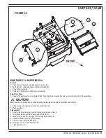
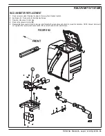
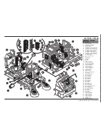
See Figure 9.1. Drain the recovery tank using the tank’s drain hose. Unlatch the recovery tank latch, swing the tank open, disconnect tank full
indicator wiring harness, separate the support strap and then lift the tank off its hinge plate.
FIGURE 9.1
Содержание 56303000
Страница 17: ...FORM NO 56043096 Captor 4300B 4800B 15 FRONT WHEEL SYSTEM FIGURE 3 1...
Страница 20: ...18 FORM NO 56043096 Captor 4300B 4800B HYDRAULIC SYSTEM FIGURE 4 3...
Страница 33: ...FORM NO 56043096 Captor 4300B 4800B 31 SOLUTION SYSTEM FIGURE 7 1...
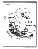
Страница 39: ...FORM NO 56043096 Captor 4300B 4800B 37 SQUEEGEE SYSTEM FIGURE 10 1...
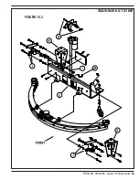
Страница 41: ...FORM NO 56043096 Captor 4300B 4800B 39 SQUEEGEE SYSTEM FIGURE 10 2...
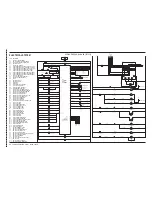
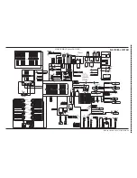
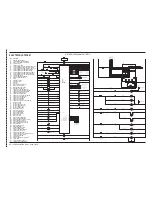
Страница 45: ...FORM NO 56043096 Captor 4300B 4800B 43 WIRING SCHEMATIC before SN 1767238 ELECTRICAL SYSTEM...
Страница 50: ......

