FORM NO. 56043096 - Captor
™
4300B, 4800B -
25
SWEEPING SYSTEM
MAIN BROOM LIFT CABLE REPLACEMENT
1
Drain the recovery tank then remove the tank completely from the machine by disconnecting its support strap and wiring connector. This is
done to access the broom cable and solution cable inspection cover.
2
Remove the inspection cover held in place by (4) screws.
3
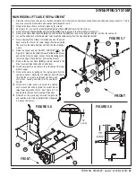
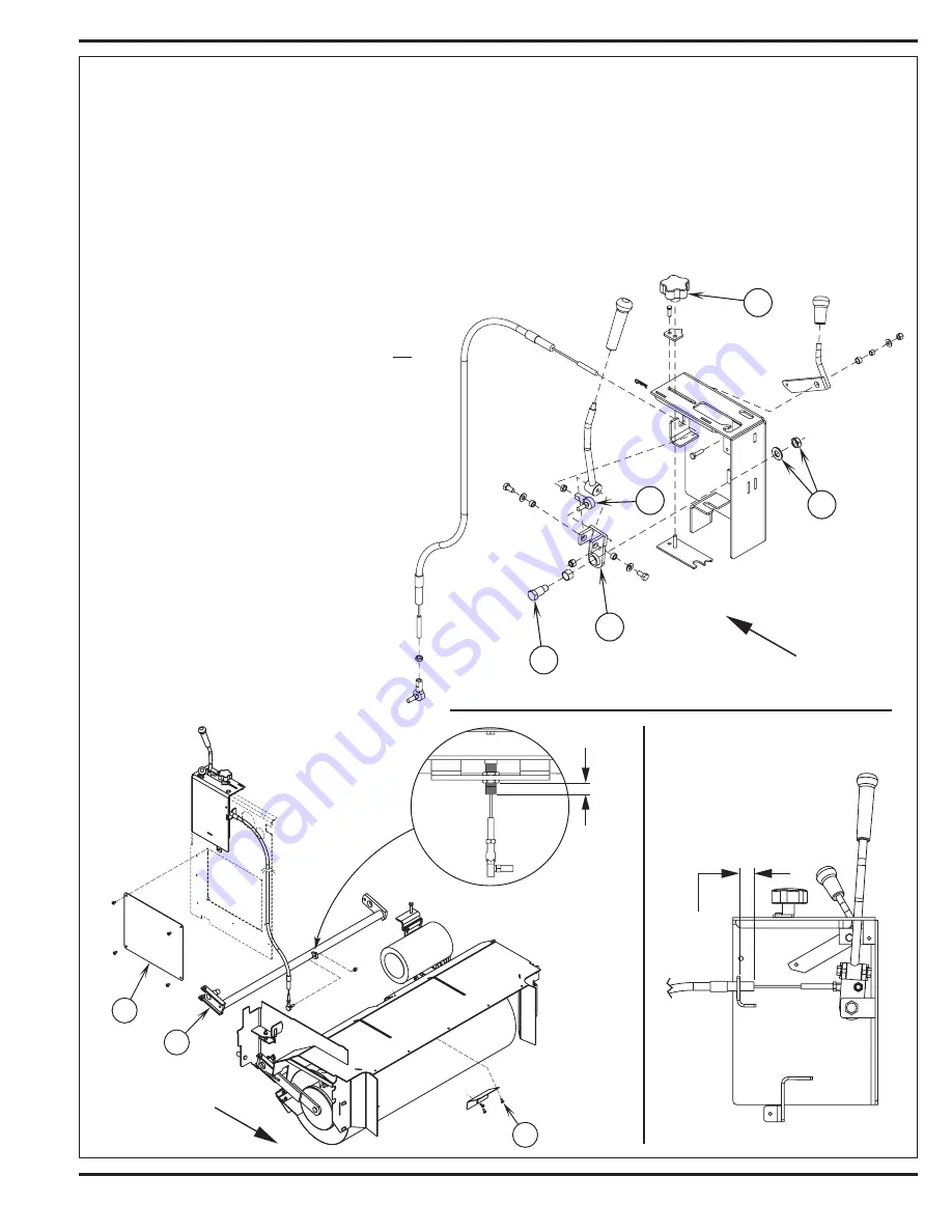
See Figure 5.7. Loosen the broom height adjustment Knob
(AP)
and lower the broom lever.
4
Remove Nut and Washer
(AQ)
and Shoulder Bolt
(AR)
to gain access to the cable ball joint connector.
5
Remove the Cable Ball Joint End
(AS)
from the Pivot Bracket
(AT)
then remove the ball joint and jam nut from the cable end.
6
Loosen the cable anchor hardware (jam nuts) & pull the cable casing from the mounting bracket slot.
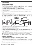
FIGURE 5.7
7
From underneath the middle of machine ahead of the scrub
deck locate the broom lift cable Hanger Weldment
(AU)
.
Then remove the cable ball joint end from the broom hanger
mount.
8
Raise the hopper and set SAFETY SUPPORT
(HH)
. See
Figure 5.8. Remove the 3
(AV)
Screws that fasten the access
panel to the broom housing. Loosen the cable casing anchor
jam nuts and pull the cable from its mounting bracket.
9
Remove the Access Panel
(AW)
(4 screws) located in the
driver’s compartment below the solution lever.
10
Attach securely the new cable to the old cable at the lower
broom hanger.
11
Remove the cable by pulling on the original cable from the
operator’s handle. Guide the old cable out and at the same
time fish the new cable up through the frame and
control box opening and attach at the operator’s
handle.
12
Attach both cable ends and adjust the cable’s
anchor connector ends to obtain the correct broom
raise/lower operational limits. See Figure 5.9 for
approximate cable anchor mounting dimensions.
13
Reinstall all the previously removed components
and reset the correct broom pattern width of between
2-3 inches (50-75mm).
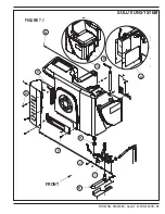
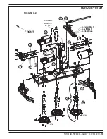
FIGURE 5.8
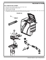
FIGURE 5.9
Содержание 56303000
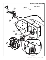
Страница 17: ...FORM NO 56043096 Captor 4300B 4800B 15 FRONT WHEEL SYSTEM FIGURE 3 1...
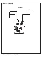
Страница 20: ...18 FORM NO 56043096 Captor 4300B 4800B HYDRAULIC SYSTEM FIGURE 4 3...
Страница 33: ...FORM NO 56043096 Captor 4300B 4800B 31 SOLUTION SYSTEM FIGURE 7 1...
Страница 39: ...FORM NO 56043096 Captor 4300B 4800B 37 SQUEEGEE SYSTEM FIGURE 10 1...
Страница 41: ...FORM NO 56043096 Captor 4300B 4800B 39 SQUEEGEE SYSTEM FIGURE 10 2...
Страница 45: ...FORM NO 56043096 Captor 4300B 4800B 43 WIRING SCHEMATIC before SN 1767238 ELECTRICAL SYSTEM...
Страница 50: ......


