16
- FORM NO. 56043096 - Captor
™
4300B, 4800B
HYDRAULIC SYSTEM
HYDRAULIC PUMP MOTOR REMOVAL
CAUTION!
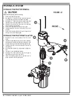
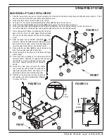
FIGURE 4.1
Disconnect the battery before servicing.
1
Remove right side battery panel.
2
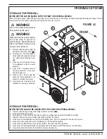
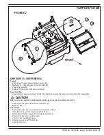
See Figure 4.2. Remove the top right side Cosmetic
Cover
(A)
and pump assembly Rubber Cover
(B)
.
3
See Figure 4.1. Remove the two hex head Screws
(C)
fastening the Pump Solenoid
(D)
to the motor frame.
4
Disconnect the 2 wires from the pump motor terminals
noting location for reconnecting.
5
Remove the 2
(E)
Bolts from the top of the motor.
6
Carefully separate the motor Frame
(F)
off the motor
armature.
7
Remove the Armature
(G)
from the pump coupler input
noting not to lose the Coupling
(H)
.
HYDRAULIC PUMP MOTOR INSTALLATION
1
Separate the new motor armature from the motor
frame.
2
Install the Coupler
(H)
onto the pump armature shaft then
carefully place armature into the pump assembly. Note
armature bearing must be flush with the pump housing.
3
Carefully place the motor Frame
(F)
and end bell over
the armature.
4
Seat the carbon brushes by compressing 2 springs at a
time.
5
Insert the 2 motor Bolts
(E)
and tighten.
6
Reconnect the motor wires then raise the hopper to
reinstall the solenoid to the motor frame.
7
Install all remaining panels and covers then test for
proper operation of the hopper system.
Содержание 56303000
Страница 17: ...FORM NO 56043096 Captor 4300B 4800B 15 FRONT WHEEL SYSTEM FIGURE 3 1...
Страница 20: ...18 FORM NO 56043096 Captor 4300B 4800B HYDRAULIC SYSTEM FIGURE 4 3...
Страница 33: ...FORM NO 56043096 Captor 4300B 4800B 31 SOLUTION SYSTEM FIGURE 7 1...
Страница 39: ...FORM NO 56043096 Captor 4300B 4800B 37 SQUEEGEE SYSTEM FIGURE 10 1...
Страница 41: ...FORM NO 56043096 Captor 4300B 4800B 39 SQUEEGEE SYSTEM FIGURE 10 2...
Страница 45: ...FORM NO 56043096 Captor 4300B 4800B 43 WIRING SCHEMATIC before SN 1767238 ELECTRICAL SYSTEM...
Страница 50: ......


