FORM NO. 56043096 - Captor
™
4300B, 4800B -
13
WHEEL DRIVE SYSTEM
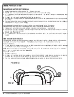
DRIVE PEDAL PIVOT NEUTRAL ADJUSTMENT
If the drive pedal pivot has been removed or replaced, the neutral position for the pedal will have to be set. Follow the steps below to accomplish
this.
WARNING!
Disconnect the machine’s battery pack connector
(13)
before servicing.
Note:
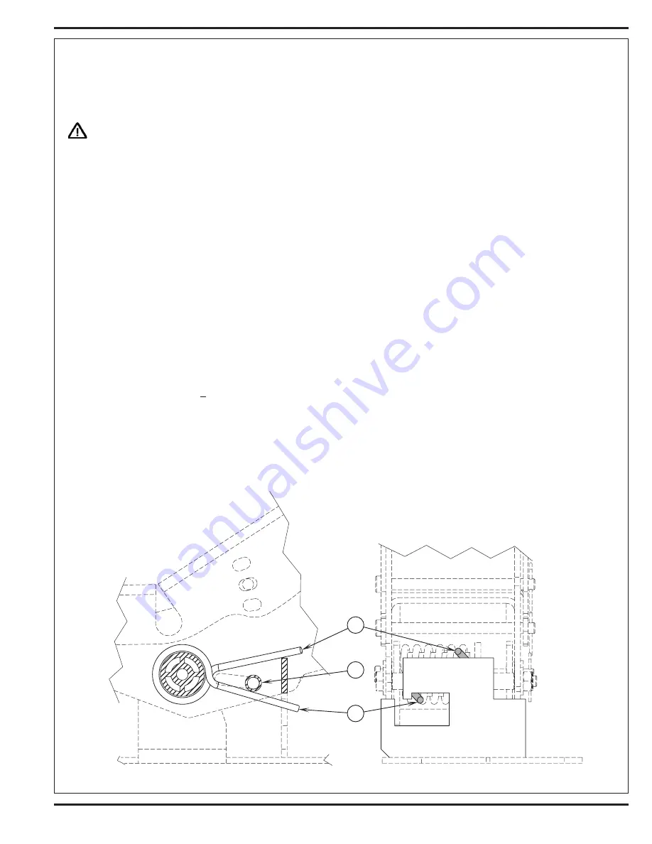
See Figures 2.3 & 2.4. Before making any adjustments, inspect the Torsion Spring
(R)
for defects and the correct positions of both spring
ends (repair or replace).
To Adjust Pedal Spring
1
Remove the top portion of the foot pedal see Figure 2.3.
2
Loosen the Screw
(S)
& Nut
(T)
, the screw with Bushing
(U)
is positioned between both Fwd & Rev torsion spring ends. Its placement controls
the needed pre-load pressure to eliminate excessive pedal free-play and a balanced spring rate to return the pedal to a centered (neutral)
position.
3
Push the screw back into the pedal frame slot to increase spring tension and eliminate pedal free play. Then tighten the screw & nut being
careful not to pull on the linkage connection to the pot shaft and disturb (move) its neutral setting.
To Replace Pedal or Spring
4
Position the torsion spring ends (
V
&
W
) as shown. This is with the bushing and screw not installed.
5
Place the bushing inside the pedal channel pilot it into position using a scratch awl or a pin punch.
6
Then pivot (press) the pedal and insert the screw from the opposite side pushing the guide tool out.
7
Use a screwdriver to tap and pry the bushing back in the pedal slot to increase spring tension.
8
Work the bushing back & forth on both sides of the pedal to obtain equal spacing. Then tighten the screw and nut.
9
A correctly adjusted drive pedal will have minimal amount of free-play when selecting a drive direction.
10
Reconnect the batteries and test the machine to make sure it does not “creep” forward or reverse when the pedal returns to neutral.
11 Service Tip:
Also confirm the
(E)
MIL (wrench) is not flashing an error code (drive system fault). If an error is shown the throttle is not set
properly for the Rotary Sensor’s neutral position. See above instructions for proper adjustment.
Operator pedal height and angle adjustments
1
Pull both pins out and reinstall in a new position to obtain a different angle to relieve operator foot fatigue.
FIGURE 2.4
Содержание 56303000
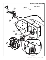
Страница 17: ...FORM NO 56043096 Captor 4300B 4800B 15 FRONT WHEEL SYSTEM FIGURE 3 1...
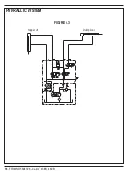
Страница 20: ...18 FORM NO 56043096 Captor 4300B 4800B HYDRAULIC SYSTEM FIGURE 4 3...
Страница 33: ...FORM NO 56043096 Captor 4300B 4800B 31 SOLUTION SYSTEM FIGURE 7 1...
Страница 39: ...FORM NO 56043096 Captor 4300B 4800B 37 SQUEEGEE SYSTEM FIGURE 10 1...
Страница 41: ...FORM NO 56043096 Captor 4300B 4800B 39 SQUEEGEE SYSTEM FIGURE 10 2...
Страница 45: ...FORM NO 56043096 Captor 4300B 4800B 43 WIRING SCHEMATIC before SN 1767238 ELECTRICAL SYSTEM...
Страница 50: ......


