background image

Configuring Your IAD

NetVanta 950 IAD Configuration Guide

 32

© 2004 ADTRAN, Inc.

61200788L1-29.1B

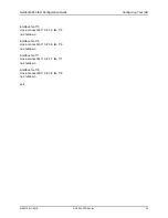
Example 4:  4 Channels of Robbed-Bit signaling to a T1 Interface

This example connects four channels from T1 0/2 to four channels on T1 1/1. They will be robbed-bit 
signaling. The NetVanta 950 is loop timed from T1 0/1. The settings in this example are common, and 
most of the settings are the default settings.

Step

Command

Description

1

IAD> enable

Enter Enable Security mode

2

IAD# configure terminal

Enter Global configuration mode

3

IAD (config)# interface t1 0/2

Enter configuration mode for T1 interface 0/2

4

IAD (config-t1 0/2)# tdm-group 2 

timeslots 13-16

Create a TDM group of timeslots 13 through 16 

on T1 0/2

5

IAD (config-t1 0/2)# no shutdown

Activate T1 0/2

6

IAD (config-t1 0/2)# exit

Exit to Global configuration mode

7

IAD (config)# interface t1 1/1

Enter configuration mode for T1 interface 1/1

8

IAD (config-t1 1/1)# tdm-group 1 

timeslots 1-4

Create a TDM group of timeslots 1 through 4 on 

T1 1/1

9

IAD (config-t1 1/1)# no shutdown

Activate T1 1/1

10

IAD (config-t1 1/1)# exit

Exit to Global configuration mode

11

IAD (config)# clock source t1 0/1

Set the system clock source to T1 interface 0/1

12

IAD (config)# cross-connect 37 t1 0/2 2 

t1 1/1 1 rbs

Create a connection between T1 0/2 TDM group 

2 and T1 1/1 TDM group 1 and preserves 

robbed-bit signaling

13

IAD (config)# exit

Exit Global configuration mode

This configuration must be saved to maintain settings after a unit reboot. Type 

copy 

running-config startup-config

 to save the running configuration to the start-up 

configuration.

The same script may be used for four channels of clear channel instead of robbed-bit 
signaling by omitting the 

rbs

 flag on the cross-connect command.

Содержание NetVanta 900 Series

Страница 1: ...settings and provides online guidance and explanations for each setting However use of the AOS CLI may be necessary for more advanced configurations Access the AOS CLI via the CONSOLE port or a Telne...

Страница 2: ...788L1 One NetVanta 950 T1 V 35 Expansion Module P N 1200798L1 Five NetVanta 900 Series Octal FXS Access Modules P N 1200791L1 One NetVanta 900 Series Octal FXO Access Module P N 1200792L1 Figure 1 sho...

Страница 3: ...ce ports connect to the right side of the chassis shown in Figure 2 Figure 2 NetVanta 950 IAD Right Side Panel Layout The T1s connect to the left side of the chassis as shown in Figure 3 Figure 3 NetV...

Страница 4: ...e CLI 2a Configuring your IAD with the Web GUI You can configure your IAD with the interactive Web GUI The web based GUI lets you configure the main settings and provides online guidance and explanati...

Страница 5: ...figuration Guide Configuring Your IAD 61200788L1 29 1B 2004 ADTRAN Inc 5 T1 Ports When you log into the Web GUI the GENERAL SYSTEM INFORMATION page displays in your browser window Figure 5 General Sys...

Страница 6: ...tion Guide 6 2004 ADTRAN Inc 61200788L1 29 1B In the left column select PHYSICAL INTERFACES and the screen shown in Figure 6 displays This screen shows all the physical interfaces that are installed i...

Страница 7: ...ays as shown in Figure 7 Figure 7 Configuration for T1 0 1 By default the T1 interface is set for ESF framing and B8ZS coding If you want to change settings select different options from the pulldown...

Страница 8: ...and errors on data circuits Options include INTERNAL t1 0 1 or t1 0 2 The default clock source is t1 0 1 Change the clock source by clicking on the PRIMARY CLOCK SOURCE menu and selecting another opti...

Страница 9: ...e configuration box shown below You can assign 24 DS0s to a T1 interface by selecting a DS0 RANGE of 1 to 24 as shown in Figure 10 For the CONNECT TO field select t1 0 1 For the STARTING DS0 select 1...

Страница 10: ...on Settings Settings Click on ENABLE to enable the interface The interface is disabled by default The receive gain is configurable in 0 1 dB increments from 12 dB to 6 dB default is 3 dB Receive gain...

Страница 11: ...wer Supervision and transmit the appropriate signaling bits on the T1 The LSAS signaling is defined as 0100 for ESF or 01 00 for D4 The carrier must configure the network T1 for LSAS if this is not a...

Страница 12: ...tion Settings Settings Click on ENABLE to enable the interface The interface is disabled by default The receive gain is configurable in 0 1 dB increments from 12 dB to 6 dB default is 0 dB Receive gai...

Страница 13: ...he T1 The LSAS signaling is defined as 0100 for ESF or 01 00 for D4 The carrier must configure the network T1 for LSAS if this is not a point to point T1 Signaling Loop start signaling bridges tip and...

Страница 14: ...LOG PORTS page Figure 13 shows the analog ports in the system This is a subset of the PHYSICAL INTERFACES page From here you can go to the individual port page for configuration just as you did from t...

Страница 15: ...00788L1 29 1B 2004 ADTRAN Inc 15 Connections The CONNECTIONS SUMMARY page Figure 14 shows every TDM connection in the system You can go to the individual port page for configuration just as instructed...

Страница 16: ...current configuration download the configuration from the IAD to your PC or upload a new configuration to the IAD When you are finished select LOGOUT at the top of the page to log out of the Web GUI F...

Страница 17: ...2 prompt for T1 WAN 0 2 See Verifying Your Configuration Using Show Commands on page 36 section for more information on the status of the T1 port Clock Source The clock source provides the reference p...

Страница 18: ...tone to enable dial tone and type ringback to enable ringback They should be enabled whenever the central office switch does not provide those features They are only necessary in E M applications and...

Страница 19: ...can be activated simultaneously To activate each port one at a time first enter interface fxs 2 1 from the Global configuration mode Type no shutdown Then type interface fxs 2 2 to move to the next po...

Страница 20: ...Type rx gain 10 to set the receive gain to 10 dB for example The transmit gain is also configurable in 0 1 dB increments from 6 dB to 10 dB default is 0 dB Transmit gain determines the amplification o...

Страница 21: ...subsequently Note that the range command also works with the cross connect command The format of the command is very similar to the individual command cross connect range A t1 slot port TDM group star...

Страница 22: ...Interface on page 32 Sample Script on page 33 8 Channels of FXO Loop Start Signaling Step by step configuration 8 Channels of FXO Loop Start Signaling on page 33 Sample Script on page 34 Configuration...

Страница 23: ...ce 0 1 4 IAD config t1 0 1 tdm group 1 timeslots 1 12 Create a TDM group of timeslots 1 through 12 on T1 0 1 5 IAD config t1 0 1 no shutdown Activate T1 0 1 6 IAD config t1 0 1 exit Exit to Global con...

Страница 24: ...no shutdown interface fxs 2 5 cross connect 5 t1 0 1 1 5 fxs 2 5 no shutdown interface fxs 2 6 cross connect 6 t1 0 1 1 6 fxs 2 6 no shutdown interface fxs 2 7 cross connect 7 t1 0 1 1 7 fxs 2 7 no sh...

Страница 25: ...fig t1 0 1 no shutdown Activate T1 0 1 6 IAD config t1 0 1 exit Exit to Global configuration mode 7 IAD config clock source t1 0 1 Set the system clock source to T1 interface 0 1 8 IAD config interfac...

Страница 26: ...nnect 15 t1 0 1 2 15 fxs 3 7 no shutdown interface fxs 3 8 signal ground start cross connect 16 t1 0 1 2 16 fxs 3 8 no shutdown interface fxs 4 1 signal ground start cross connect 17 t1 0 1 2 17 fxs 4...

Страница 27: ...ersed when the remote equipment ends the call The NetVanta 950 is loop timed from T1 0 1 previously connected Step Command Description 1 IAD enable Enter Enable Security mode 2 IAD configure terminal...

Страница 28: ...ff hook condition 14 IAD config fxs 5 1 8 fxs 6 1 4 dial tone Configures the FXS interfaces to provide dial tone 15 IAD config fxs 5 1 8 fxs 6 1 4 ringback Configures the FXS interfaces to provide rin...

Страница 29: ...attery reverse dnis wink timeout dnis delay 1000 dial tone ringback cross connect 25 t1 0 2 1 1 fxs 5 1 no shutdown interface fxs 5 2 em conversion wink forward disconnect delay 1000 forward disconnec...

Страница 30: ...ingback cross connect 29 t1 0 2 1 5 fxs 5 5 no shutdown interface fxs 5 6 em conversion wink forward disconnect delay 1000 forward disconnect battery reverse dnis wink timeout dnis delay 1000 dial ton...

Страница 31: ...wink forward disconnect delay 1000 forward disconnect battery reverse dnis wink timeout dnis delay 1000 dial tone ringback cross connect 34 t1 0 2 1 10 fxs 6 2 no shutdown interface fxs 6 3 em conver...

Страница 32: ...config t1 0 2 exit Exit to Global configuration mode 7 IAD config interface t1 1 1 Enter configuration mode for T1 interface 1 1 8 IAD config t1 1 1 tdm group 1 timeslots 1 4 Create a TDM group of ti...

Страница 33: ...mple is the most common and most of the settings are the default settings The same script may be used for four channels of clear channel instead of robbed bit signaling by omitting the rbs flag on the...

Страница 34: ...3 3 fxo 7 3 no shutdown interface fxo 7 4 cross connect 41 t1 0 2 3 4 fxo 7 4 no shutdown 9 IAD config fxs 7 1 8 no shutdown Activate all FXO interfaces from Slot 7 1 to Slot 7 8 10 IAD config fxs 7 1...

Страница 35: ...DTRAN Inc 35 interface fxo 7 5 cross connect 42 t1 0 2 3 5 fxo 7 5 no shutdown interface fxo 7 6 cross connect 43 t1 0 2 3 6 fxo 7 6 no shutdown interface fxo 7 7 cross connect 44 t1 0 2 3 7 fxo 7 7 n...

Страница 36: ...larm 0 Remote alarm 0 DS0 Status 1 2 3 4 5 6 7 8 9 0 1 2 3 4 5 6 7 8 9 0 1 2 3 4 N N N N N N N N N N N N N N N N N N N N N N N N Status Legend DS0 is unallocated N DS0 is dedicated nailed Signaling Bi...

Страница 37: ...vailable IN TEST Port is in test mode Two wire Status is Disabled Test Status is INACTIVE No Tests Impedance is 600 Ohm 2 16uF Transmit Gain is 0 0dB Receive Gain is 10 0dB Signal Mode Loop Start Answ...

Страница 38: ...nfig t1 0 2 prompt Interface Command Description T1 loopback network line Initiates an internal physical loopback of the local T1 circuit T1 loopback network payload Initiates an internal loopback of...

Страница 39: ...kHz test tone toward the analog phone interface FXS test tone far Sends a 1kHz test tone toward the network interface FXS no test tone Deactivates test tone FXS test battery Provides battery on the an...

Страница 40: ...e Command Description FXO loopback analog Initiates an internal loopback toward the 2 wire interface FXO loopback digital Initiates an internal loopback toward the network interface 4 wire interface F...

Страница 41: ...for example There are additional management options available for event history storage email notification and syslog forwarding You can use the following commands to set an explicit priority level f...

Страница 42: ...d Detected FXS Debug Ringing Test Offhook Detected FXS Debug Battery Test Offhook Detected FXS Debug Battery Test Onhook Detected FXS Debug Ringing Test Ring Ground Detected FXS Debug Card Initialized...

Страница 43: ...est Ring Ground Detected FXO Debug Card Initialized FXO Debug Changed state to up down administratively down testing T1 Error No Alarms Yellow Tx Yellow Blue Tx Blue Red LOS Loopback No Signaling T1 W...

Отзывы: