2
61287800F1-13A
2. Select the appropriate mounting bracket and using the holes in the
mounting brackets as a template, mark the surface where the
screws will attach the ADTRAN 602 to the plywood surface.
3. Secure the brackets to the sides of the ADTRAN 602 using the
screws provided.
4. Secure the ADTRAN 602 to the plywood using two #6 to #10 wood
screws, at least 3/4” in length.
Step 2: Ground the ADTRAN 602
To ground the ADTRAN 602, refer to the illustration on the first page and
complete the following steps:
1. Attach a minimum 18
ground strap to the Chassis Ground
using a UL approved ring lug and anti-rotational device (star
washer).
2. Tighten the ground strap using the 1/4 inch nut supplied with the
ADTRAN 602.
3. Connect the other end of the ground strap to a known, reliable
ground at the installation site/location.
4. Using an ohmmeter, verify continuity between the ground lug and
known good frame ground. The reading should be less than 1 ohm.
Step 3: Clean the LAN or WAN Connections
To clean the Customer
connections for the ADTRAN 602,
refer to the illustration on the first page and complete the following steps:
1. Clean Optical interfaces of the appropriate SFP+/XFP.
f
CAUTION!
■
Do not allow disconnected optical connectors to touch surrounding
unrelated surfaces and do not touch optical surfaces for any reason
other than while performing the cleaning process.
■
Do not use compressed air to clean optical connectors.
■
Clean the optical surfaces as follows:
♦
Use a fiberscope or videoscope to verify proper cleaning of
connectors prior to connecting components together.
♦
Use pure alcohol (reagent grade, 99.5% pure) when cleaning the
endface of connectors. The alcohol can be applied with either
laboratory grade lint-free tissues or with pre-moistened optical
grade wipes.
♦
Use microporous fabric spiral wrapped cleaning tips to clean
bulkhead ferrules.
g
NOTE
The following are guidelines for installing the
■
The latch on the SFP/XFP is for removal only. When removing the
SFP/XFP, rotate the latch away from the SFP/XFP cage until a
physical click occurs. The SFP/XFP should slide easily out of the cage.
■
Always have dust caps and dust plugs installed when connectors or
adapters are not mated. Store dust caps in a sealable plastic bag
when not in use.
Step 4: Install SFP+ or XFP
To install the SFP+ or XFP, complete the following steps:
1. Insert the appropriate SFP+ or XFP into the appropriate cage with
the latch handle facing outward. Slide the SFP+ or XFP all the way
into the SFP cage.
2. Using thumb and forefinger, exert adequate pressure to ensure the
SFP+ or XFP is completely seated in the cage.
■
Phillips-head screw driver
■
Assorted tie wraps for securing cabling and wiring
For fiber optic connections, the following are required:
■
Fiber optical fusion splice tools
■
■
Fiber connector
Installation Steps
To install the ADTRAN 602, complete the following steps.
Step 1: Locate the ADTRAN 602
There are three options to install the ADTRAN 602: Desk Top, Rack
Mount, and Wall Mount. All options are described below.
g
NOTE
Included with the ADTRAN 602 is a 4-foot power cord. All installation
locations should be within 4-feet of a wall outlet.
Desk Top Installation
The ADTRAN 602 can be located on a desktop.
f
WARNING!
Ensure that the ADTRAN 602 does not come in contact with water or other
liquids.
f
CAUTION!
Ensure that the ADTRAN 602 is not located in direct sunlight or next to
any thermal obstructions.
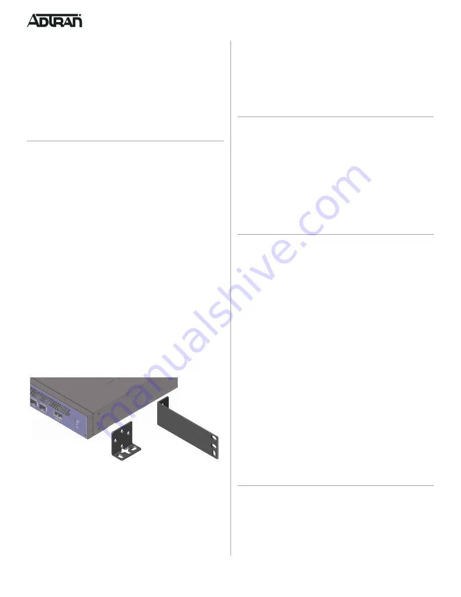
Rack Mount Installation
Refer to
and perform the following steps:
1. Select the appropriate mounting bracket and secure it to the side of
the ADTRAN 602 in the orientation desired using the screws pro-
vided.
2. Secure the ADTRAN 602 to a rack using the appropriate mounting
screws.
Figure 1. Attach Mounting Brackets
Wall Mount
Refer to
and perform the following steps:
1. Prepare the mounting surface by attaching a board (typically ply-
wood, 1/4” to 1/2” thick) to the wall studs using appropriate lag bolts.
Mounting Bracket
(P/N: 3265479-2E@E)
Mounting Bracket
(P/N: 3265937-1E@C)


