background image


QS2 Series Low-voltage Servo 

Drive


55 


Chapter 7 Operation  

After finishing install and line connecting, check the following items prior to power 
connection:  

Are the sub-lines correct or fixed? Is the input voltage correct? 

Is there a short circuit in power line or motor line? 

Has the control signal terminal been properly connected? Is the power polar or the 

current magnitude correct? 

Have the drive and the motor been fixed firmly? 

Does the motor connected load?  

Does the motor and the drive assort with each other in specification? 


7.1 

Position control 


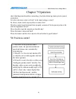
1. When P4=0, the system is under 
position mode, the operation rotational 
speed and distance are controlled by 
external pulse. 
2. When P=5 or the external interface EN 
is valid, the servo enable signals valid and 
the motor operates. 

4. When P6 is not 0, the drive will be set to  

“intelligent position mode” forcibly. The  
Rigidity of the system can be modified by  

modifying P6, without modifying P16, P21 

or P22. (Note: only version higher than  

1010 has intelligent mode. And the  

parameter management software of upper  

machine matched must be version 1.05.)

Содержание QS2 Series

Страница 1: ...QS2 Series Low voltage Servo Drive...

Страница 2: ...of imitation copying transcription or translation by any company or individual without the permission is prohibited This manual does not include any form of assurance standpoint expression or other i...

Страница 3: ...ring with the parts list or damages situation Contact our company promptly for discrepant models shortage accessories or transport damages Wiring Ensure the persons involved into wiring and inspecting...

Страница 4: ...n if processing field is in high temperature due to close relationship between service life of the control and environmental temperature Keep proper operative temperature range for the control 0 60 Av...

Страница 5: ...nd Dimensions 12 2 2 Installation of Servo Motor 13 2 2 1 Installing Environmental Conditions 13 2 2 2 Definition of Motor Rotation Direction 14 Chapter 3 Wiring 15 3 1 Overall Wiring Diagram 15 3 2 N...

Страница 6: ...35 Chapter 6 Parameter Adjustment of Low voltage Servo Drive 39 6 1 Parameter List 39 6 2 Explanation of Parameter in Detail 42 6 3 Adjustment of PID Parameter 53 6 4 Adjustment of Other Parameters 5...

Страница 7: ...below after opening Items Reference Methods Whether the model of the product is the same as the ordered one Please check through the nameplate of the servo motor and servo drive Whether the rotation...

Страница 8: ...CL 06 020 A 1 A A 11 Axis diameters 36V A 36 B 14 Axis diameters 200W B 60 60 Flanges 1 1000 wire encoder Low voltage AC Servo 2 2500 wire encoder For example ACL06020B 2B represents 60 flange 200W 60...

Страница 9: ...nology Advanced FOC algorithm technology SCPWM space vector control Input power supply DC24V 80V Feedback Incremental 2500 wire photoelectric revolving encoder Conditions of Use Operating storage temp...

Страница 10: ...control method Output signal Position completion servo alarm Built in functions Protection function Over current overvoltage under voltage overload encoder exception and other alarms Monitoring funct...

Страница 11: ...e installed in the control cabinet retain sufficient space to help the flow of air to help cooling please install a fan to reduce the temperature around the drive to ensure long term safety the operat...

Страница 12: ...e is vertical or horizontal Mounting and fixing Use two vertical mounting holes four horizontal mounting holes and tighten with screws Ventilation use natural cooling cooling fan must be installed in...

Страница 13: ...15 U 8 Z SW3 SW4 OFF RS232 OFF 9600 bps ON RS485 ON config 5 Drive size unit mm AC servo drive QS208020M I O COM1 Modleselect Encode COM2 SW4 SW3 SW2 SW1 24 80 VDC M 10 1 9 15 11 26 GND VCC BR Encode...

Страница 14: ...mended to be loaded with flexible coupling Motor shall be secured with nut lock washer to prevent motor loosening 2 2 2 Definition of Motor Rotation Direction Facing to the motor shaft extension forwa...

Страница 15: ...tage Servo Drive Chapter 3 Wiring 3 1 Overall Wiring Diagram 1 Overall wiring diagram of QS2 Series is as shown in the figure below Communication wire Control wire Brake resistance Encoder wire Switch...

Страница 16: ...QS2 Series Low Voltage Servo Drive 2 Explanation of wire specification Motor model Requirement on wire diameter Main power Motor power cable Encoder and control signal wire 200W 1 25mm2 1 25mm2 0 14m...

Страница 17: ...he power cable strong electricity circuit such as power wire motor wire over 30cm away from the signal wire Do not put the two wires in the same conduits Please install the non fusion circuit breaker...

Страница 18: ...is connected between VDC and BR 2 Terminal of motor power cable No Code Color Signal function 1 W Black Motor UVW 2 V Green 3 U Red 4 PE Yellow Connected with motor housing 3 Terminal of CN1 controlle...

Страница 19: ...mit 2 PLUS Positive pulse signal 15 INCOM Power positive 3 NC NC reserved 16 OUTCOM Common port of output signal 4 EN Negative input of enable single end differential input 17 OB Encoder B 5 EN Positi...

Страница 20: ...t used in single end input 25 OA Encoder A 13 CCW Reverse limit 26 OA Encoder A 4 Encoder feedback signal terminal The board terminal CN2 is the socket component for DB15 on the receptacle QS2 series...

Страница 21: ...5 U U signal input 5 Communication interface COM1 COM2 Port base Connector COM1 COM2 Pin No Signal name Pin No Signal name 1 GND 1 GND 2 RXD 2 RXD 3 TXD 3 TXD 4 RS485 4 RS485 5 RS485 5 RS485 6 VCC 6 V...

Страница 22: ...itch EN MODE CW CCW ALRS input interface Switch EN MODE CW CCW ALRS input interface 1 DC 12V 24V 2 Current is less than 20mA 3 Polarity reverse of power supply will cause servo drive damage 4 Inductiv...

Страница 23: ...up resistor shall be selected according to the user s system The empiric value VCC 12V R 1K 1 4W is recommended VCC 24V R 2K 1 4W is recommended 3 Inverse connection of power supply would damage the...

Страница 24: ...gle end common cathode input connection Upper comp uter PLC 24 V INPLCCOM 12 2K PULS PULS 2K Drive SIGN SIGN 2 24V single end common anode input connection Upper comp uter PLC 24 V INPLCCOM 12 2K PULS...

Страница 25: ...bishi PLC wiring cases and the company s wiring cases 3 3 4 Analog Quantity input interface Input of speed analog quantity and torque analog quantity 10V Speed instruction input Drive 10V rated rotati...

Страница 26: ...4 4 4 Overvoltage of hardware 5 5 5 Over current of hardware 6 6 6 Overvoltage of software 7 7 7 Limit alarm 8 8 8 Reserved by manufacturer 9 8 9 Position deviation alarm 10 8 16 Reserved by manufactu...

Страница 27: ...ON Note1 Switch1 and 2 are for the selection of pulse mode Switch 3 is for the selection of communication mode and Switch 4 is for the selection of communication baud rate and communication station nu...

Страница 28: ...e convenience of USB RS232 485 we will explain with it 5 1 Installing USB RS485 RS232 Drive Insert the drive CD into the CD ROM and click on the CD ROM to show the following folder Below is the exampl...

Страница 29: ...ive Click OK to pop up the window select Hardware Device Manager and click OK Click Ports COM LPT to view the COM port of the computer allocated for the drive write down the COM number and use to conn...

Страница 30: ...30 QS2 Series Low Voltage Servo Drive If the COM isn t between COM1 COM6 please change as follows...

Страница 31: ...31 QS2 Series Low Voltage Servo Drive In the pop up dialog box select the Port Settings Advanced and click OK In the pop up window select a COM port within 1 6 and click OK step by step...

Страница 32: ...the software 5 2 Open the drive software and set parameters 1 The communication baud rate and the communication baud rate in the drive can be set by dial switch The baud rate of parameter management s...

Страница 33: ...he motor to communicate after setting of the communication parameters 5 3 Parameter settings 1 After connecting the communication successfully the basic state of the motor running is displayed on the...

Страница 34: ...34 QS2 Series Low Voltage Servo Drive 2 Click Drive Parameters and enter the parameter modification interface...

Страница 35: ...example of the steps to change the baud rate of the drive from 9600 to 115200 1 The baud rate is 9600 port is COM3 communication is RS232 and communication connection is OK 2 At this time you can see...

Страница 36: ...36 QS2 Series Low Voltage Servo Drive 3 After changing P44 to 7 click OK to modify and you can see that P44 has been changed to 7 in Drive Values on the left...

Страница 37: ...2 Series Low Voltage Servo Drive 4 Click Cure parameters to cut off power of the drive 5 SW4 is changed from 0 off to 1 on and is powered up normally after connecting the drive Communication mode is R...

Страница 38: ...es Low Voltage Servo Drive 6 Re open QS Servo Drives Parameters Management Software select the communication baud rate to 115200 select the correct port COM3 click Connect and the communication connec...

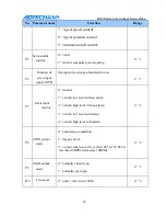
Страница 39: ...4 with normal connection P4 Control mode P S T 0 9 0 P5 Servo enable control P S T 0 1 0 P6 Function of servo input INTH Function of reservation P7 Limit input control P 0 4 0 P8 Coin output mode P S...

Страница 40: ...ro voltage S T 0 P30 Inertia ratio P T S 0 1000 0 P31 Analog input percentage S T 0 500 0 P32 Encoder wire number frequency division P S T 0 127 0 P33 Encoder alarm permission P S T 0 1 0 P34 JOG spee...

Страница 41: ...type P S T 0 1 0 P54 Number of pole pairs P S T 2 6 4 P55 Deviation angle P S T 0 2500 210 P56 Rated current P S T 0 100 28 0 1A P57 Rated torque P S T 0 200 13 0 1NM P58 Second electron gear numerato...

Страница 42: ...parameters according to the motor P52 encoder wire P53 encoder type P54 pole pairs P55 deviation angle P56 rated current P57 rated torque P3 UVW value The motor rotor rotates clockwise indicating 5 1...

Страница 43: ...rt reservation function for now 0 1 P7 Limit input control 0 invalid 0 4 1 valid in low level with no alarm 2 valid in high level with no alarm 3 valid in low level with alarm 4 valid in high level wi...

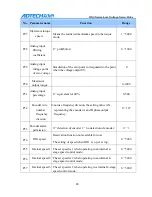
Страница 44: ...tion of position command pulse electronic gear In electronic gear ratio control mode set parameter P12 and P13 to easily achieve pulse equivalent matching considering that the acceptable frequency ran...

Страница 45: ...e supposed that the positioning has been done and the signal with COIN ON otherwise with COIN OFF 0 32000 P15 Alarm range for position over weight When set as 0 the over weight alarm detection is inva...

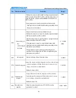
Страница 46: ...f exponential form The value means the acceleration and deceleration 0 1000 The filtering will not lose pulse but has phenomenon of instruction delay Mainly used in The upper computer controller witho...

Страница 47: ...s and larger the inflexibility is 1 32000 P23 Acceleration time speed The setting value represents the acceleration time of the motor from 0 to 1 000R MIN 0 32 000 MS The feature of acceleration and d...

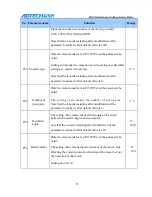
Страница 48: ...r wire number frequency division 0 not use frequency division the setting value is N representing the encoder A and B phase output frequency 0 127 P33 Encoder alarm permission 0 detection of encoder 1...

Страница 49: ...ol mode 0 32000 P43 Correspondence address 1 0 255 P44 Communication baud rate 0 4800 1 9600 2 14400 3 19200 4 5 38400 6 57600 7 115200 0 7 P45 Torque arrival percentage Set the proportion between the...

Страница 50: ...d from OFF to ON This parameter is used to switch from brake shaft locking to motor enable shaft locking smoothly when the motor is electrified The parameter can be prolonged when the motor operates f...

Страница 51: ...1 P54 Number of pole pairs Only the motor model set as P2 9999 can the parameter be valid The setting value means the number of pole pairs Note that the it needs restarting after modification of the...

Страница 52: ...is too large 0 9 P61 Drive current type Reserved P62 V phase current zero point rectification value It means the float value of V phase current zero point 2008 2088 P63 W phase current zero point rect...

Страница 53: ...he position loop gain to a small value and increase the speed loop gain within a range that cause no vibration and abnormal sound 3 decrease the speed loop integral without causing vibration 4 increas...

Страница 54: ...peed mode 3 moment mode P5 Servo enable 0 motor shaft unlocked 1 motor excitation shaft locked P9 Alarm switch 0 normally closed 1 output normally open signal when alarm is detected P11 Selection of m...

Страница 55: ...connected load Does the motor and the drive assort with each other in specification 7 1 Position control 1 When P4 0 the system is under position mode the operation rotational speed and distance are c...

Страница 56: ...in 20 and pin 19 of CN1 port Revolution is VIN 10V P26 rpm 7 3 Torque control 1 When P4 3 the system is under moment mode 2 When P5 1or EN is valid the motor operates 3 When P25 1 the moment is contro...

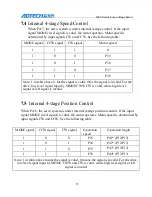
Страница 57: ...input by MODE CWW CW is valid while high level signal or left signal is invalid 7 5 Internal 4 stage Position Control When P4 8 the servo system is under internal 4 stage position control If the input...

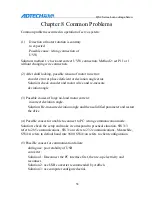
Страница 58: ...causes of large no load motor current incorrect deviation angle Solution Re measure deviation angle and then solidified parameter and restart the drive 4 Possible causes for unable to connect to PC wr...

Страница 59: ...ching power supply 8 Possible causes for that the drive cannot receive pulses and stop after short time running SW1 0 and SW2 0 the signal is filtered when its frequency is higher than 100KHz Solution...

Страница 60: ...tor ACL06010A 2A 100 36 8 501H3000001 Servo motor ACL06010A 2B 100 36 11 Material code Material name Model Remarks See the model Pulse line 26 pin head E63AG261101 No wire DB head only for customer to...

Страница 61: ...tional component applied when the inertia is large E34A1500251 Switching power supply 68V 500W be applied to 60V motor Be applied to 60V servo motor E34A1350291 Switching power supply 350W input 100 1...

Отзывы: