5
QS2 Series Low-voltage Servo Drive
Contents
Chapter 1 Product Inspection and Information
.......................................................... 7
1.1 Product Inspection ............................................................................................ 7
1.2 Naming Convention of Servo Motor and Drive ............................................... 8
1.2.1 Nomination for Servo Drive ......................................................................... 8
1.3 Reference Table of Servo Motor and Servo Drive ........................................... 8
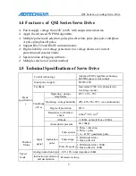
1.4 Features of QS2 Series Servo Drive ................................................................. 9
1.5 Technical Specification of Servo Drive ............................................................ 9
Chapter 2 Installation
................................................................................................. 11
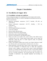
2.1 Installation of Servo Drive ............................................................................. 11
2.1.1
Installing Environmental Conditions
...................................................... 11
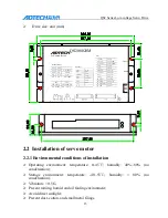
2.1.2 Installation Method and Dimensions ....................................................... 12
2.2 Installation of Servo Motor ............................................................................ 13
2.2.1
Installing Environmental Conditions
...................................................... 13
2.2.2
Definition of Motor Rotation Direction
.................................................. 14
Chapter 3 Wiring ...................................................................................................... 15
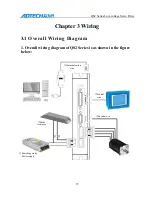
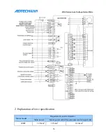
3.1 Overall Wiring Diagram ................................................................................. 15
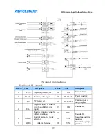
3.2 Name and Function of Terminals ................................................................... 17
3.2.1. Introduction of Interface ......................................................................... 17
3.2.2. Details on Interface ................................................................................. 18
3.3 Principle of Input and Output Interface .......................................................... 22
3.3.1 Switch EN-
,
MODE-
,
CW-
,
CCW-
,
ALRS- Input Interface ........................... 22
3.3.2
Switch ALM, COIN Output Interface
.................................................. 23
3.3.3 Pulsing Signal Inlet Interface .................................................................. 23
3.3.4 Analog Quantity Input Interface ............................................................... 25
Chapter 4 LED Alarm Indicator and Dial Switch
..................................................... 26
4.1 LED Indicator Light ........................................................................................ 26
4.1.1 Red Indicator Light ................................................................................... 26
4.1.2 Green Indicator Light ............................................................................... 26
4.2 Dial Switch ...................................................................................................... 27


