23
QS2 Series Low Voltage Servo Drive
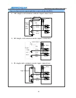
3.3.2 Switching value
ALM
,
COIN output interface
Switch
ALM, COIN output interface
Pull-up
Resistor drive
23 ALM+
Alarm output
24
COIN+
Positioning completion
16
OUT
PLC output common port
COM-
1. Power supplied by user is 12V~24VDC. The maximum signal output current is 20mA.
2. The output is in a form of open collector. The pull-up resistor shall be selected according to
the user’s system. The empiric value:
VCC=12V, R=1K, 1/4W is recommended
VCC=24V, R=2K, 1/4W is recommended
3. Inverse connection of power supply would damage the servo drive.
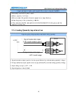
3.3.3 Pulse signal input interface
Differential input of pulse signal
Drive
Position instruction pulse PULS +2
PULS -1
Direction instruction pulse
SIGN
+10
SIGN - 11
1. Pulse frequency≤500KHz, duty ratio is 1:1, and the actually required is 0.4us
。
2. It is recommended to use differential drive mode
3. Apply AM26LS31, MC3487 or the similar RS422 wire drive

