23
POWER
LED indicator light
Indicate Host power status
SERVO ON
LED indicator light
Indicate servo enable status
RUN
LED indicator light
Indicate system running status
ALARM
LED indicator light
Indicate system alarm status
LAN
Ethernet port
Internet communication
MEM
USB2.0 port
U-disk communication
USB
USB1.1 port
USB communication
COM1
RS232 port
Series ports communication
COM2
RS232 port
Series ports communication
INPUT
Input port
IO wire boards terminal
OUTPUT
Output port
IO wire boards terminal
GND
24V Power ground
Out power supply ground
P24
24V Power positive
Out power supply positive
FUSE
Fuse
IO boards 24V fuse
3. Power Cord Connect
Main Power Supply
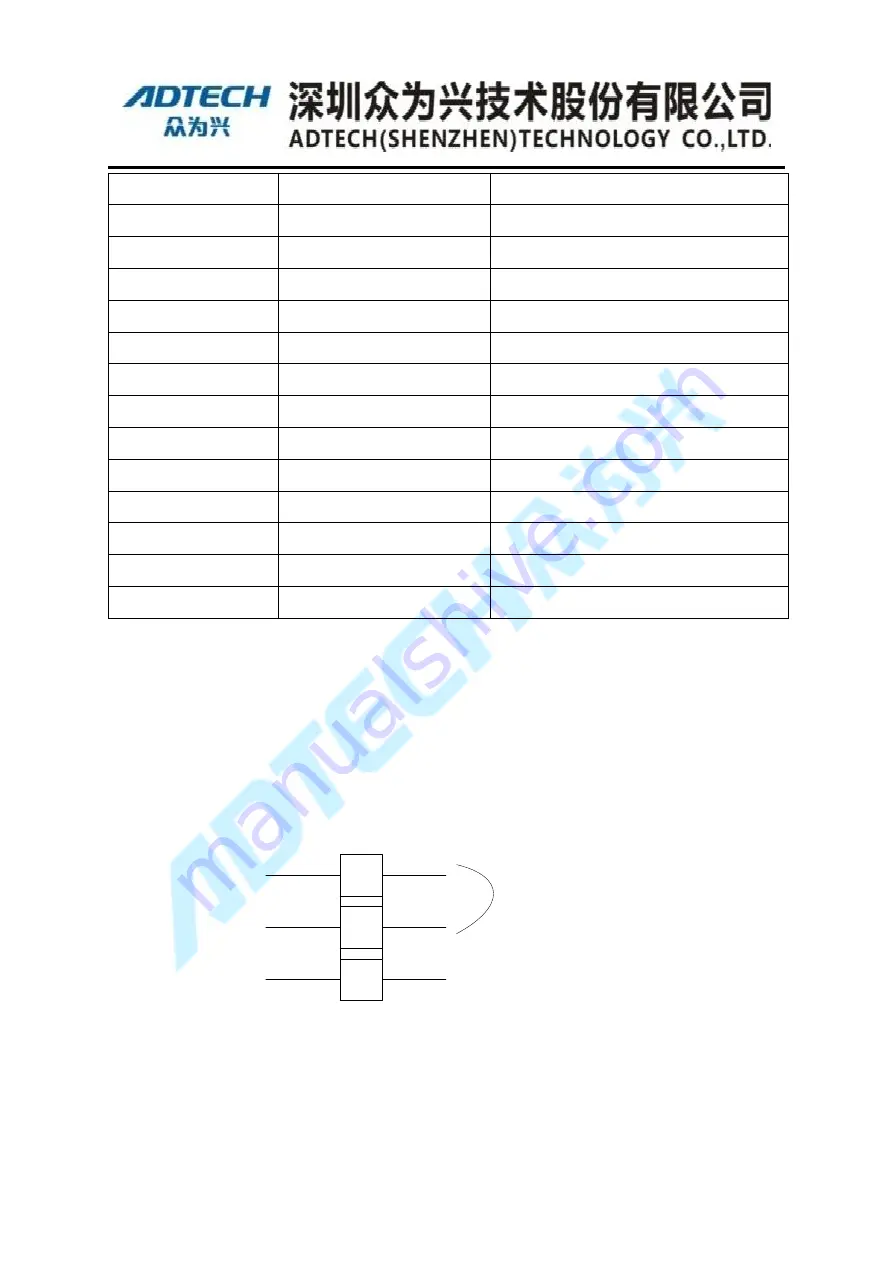
Robot driver system power cord terminal (AC IN) connect is shown as following figure
3-1:
1
2
3
L
N
PE
Single phase
AC(190~240V)
50/60Hz
R
S
FG
Figure 3-1 Power terminal diagram
Terminal spec.: 3 bit, single floor, female, distance of terminal 10.16mm, Black two
sides with lock, Total height 29mm, Power cord specification: 3 wire, 200mm,
2.5mm;
Содержание ADT-RC400
Страница 1: ...ADTECH Robotic Drive System ADT RC400 User Manual Electrical Wiring ...
Страница 11: ...X Power cord must be used with the specified wire Prone to fire and failure ...
Страница 20: ...19 Peripheral Devices SCARA Robot FlexPendant IO Board QC400 Controller Figure 2 1 System Configuration ...
Страница 45: ......


