background image

Web Console

 51

MCM-216/218

Settings may be saved as a Mission Profile (JSON file) for backup
or for convenient duplication on other 

MCM-216/218

 devices. Click

SAVE PROFILE

 to download the file to your PC. To import a Mis-

sion Profile to an 

MCM-216/218

 device, click 

Choose File

 under

Select Mission Profile

 and select the desired configuration file.

All settings will change according to that file. Alternatively, clicking

LOAD DEFAULT

 will restore all settings to their default values.

After any change to device settings, the 

APPLY

 button must be

clicked in order to activate the changes.

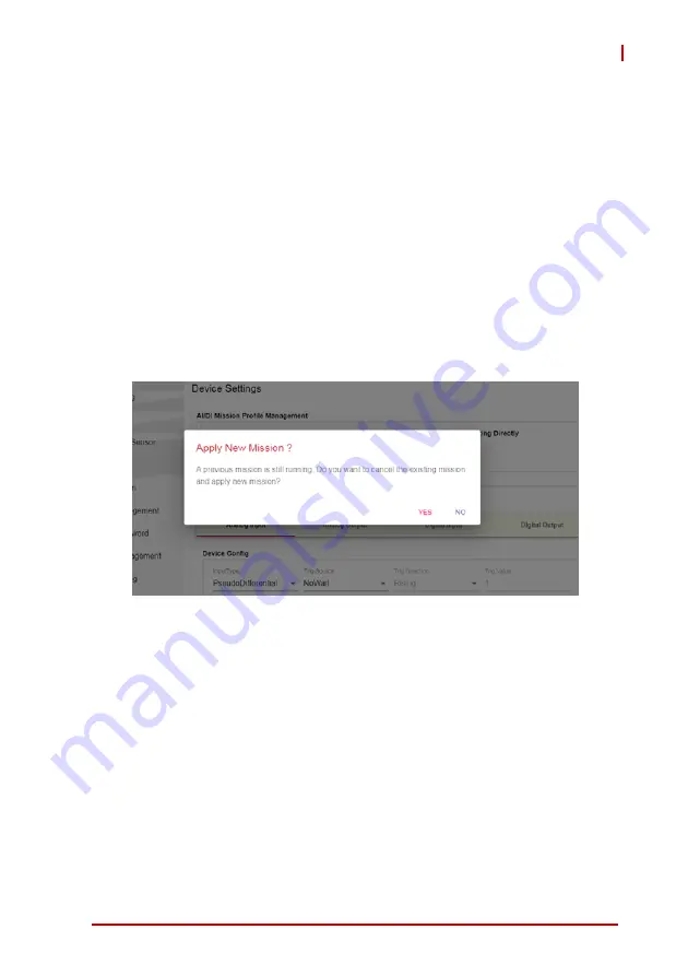
If a mission is already running while attempting to apply new
changes, a confirmation window will appear. If you’re ready for the

MCM-216/218

 to cancel its previous mission and start running the

new mission, click 

YES

.

Figure 3-30: Apply a New Mission

Содержание MCM-216

Страница 1: ...MCM 216 218 Standalone Ethernet DAQ for Distributed Machine Condition Monitoring User s Manual Manual Rev 1 0 Revision Date May 10 2021 Part No 50M 00024 1000 ...

Страница 2: ...ii Revision History Revision Release Date Description of Change s 1 0 2021 05 10 Initial Release ...

Страница 3: ...s arising out of the use or inability to use the product or documentation even if advised of the possibility of such damages ADLINK is committed to fulfill its social responsi bility to global environmental preservation through compliance with the European Union s Restriction of Hazardous Substances RoHS directive and Waste Electrical and Electronic Equipment WEEE directive Environmental protectio...

Страница 4: ...more information go to www P65Warnings ca gov Trademarks Product names mentioned herein are used for identification pur poses only and may be trademarks and or registered trademarks of their respective companies Conventions Take note of the following conventions used throughout this manual to make sure that users perform certain tasks and instructions properly NOTE NOTE Additional information aids...

Страница 5: ...5 Mechanical 5 1 3 6 Environmental 6 1 4 Mechanical Drawings 7 1 4 1 Dimensions 7 1 4 2 DIN Rail Mount 11 1 4 3 Wall Mount 12 1 5 I O Connectors 14 1 5 1 Analog Input and Analog Output 14 1 5 2 Digital Input and Output 15 1 5 3 Temperature Sensor Input 15 1 5 4 Reset Pin for Factory Default 16 1 5 5 Ethernet Ports 17 1 5 6 LED Indicators 17 1 5 7 USB Ports 17 2 Getting Started 19 2 1 Unpacking the...

Страница 6: ...al 28 3 2 3 Data Manager Data History 29 3 2 4 Mission Manager Mission Management 29 3 2 5 System Manager Change Password 30 3 2 6 System Manager Account Management 30 3 2 7 System Manager Network Setting 31 3 2 8 System Manager System Setting 32 3 2 9 Data Manger TCP Socket for one shut query mode 34 3 2 10 Device Manager Modbus TCP Server 35 3 3 DAQ Mission 40 4 DAQ Missions 53 4 1 Usage Behavio...

Страница 7: ...gure 3 9 Account Management 30 Figure 3 10 Network Settings 31 Figure 3 11 System Settings 32 Figure 3 12 Upload Customization Firmware Files 33 Figure 3 13 TCP Socket 34 Figure 3 14 Modbus TCP Server 35 Figure 3 15 Data Types for Modbus TCP 36 Figure 3 16 Modbus TCP Created Data Types 37 Figure 3 17 Data Value Starting Address Allocation 38 Figure 3 18 Modbus Function Codes 39 Figure 3 19 Device ...

Страница 8: ...viii List of Figures Figure 3 30 Apply a New Mission 51 Figure 4 1 Operational Modes 54 Figure 4 2 RESTful API 55 ...

Страница 9: ...motely by IT staff The ADLINK MCM 216 218 is a standalone Ethernet DAQ that acquires voltage and current signals from a monitored machine which represent the machine status with a threshold setting mechanism reporting important results to the backend server This in turn dramatically reduces network bandwidth traffic as well as the backend server s computing burden The MCM 216 218 is designed for o...

Страница 10: ...rver mode to upload data to SCADA system X Supports custom filtering algorithms for edge data X 8 or 16 channel 16 bit analog input up to 250 kS s X System automatically resumes its previous running state upon power recovery X 1x RS 485 port for serial communication with Modbus RTU protocol X 8 channel isolated digital input output X Two 1 Gb Ethernet ports for cascading 1 2 Applications X Distrib...

Страница 11: ...munication Interfaces Web console RESTful API TCP socket client mode Digital Temperature Sensor TI LMT01 50 C to 150 C with 3 meter cable Analog Input Specifications Number of Channels 8 for MCM 218 16 for MCM 216 Resolution 16 bit Maximum Sampling Rate 250 kS s and can be shared by selected channels 100 KHz for multi channel gain queue Input Range voltage 10V 2 5V 1 25V 312 5mV Input Range curren...

Страница 12: ... Diff SINAD 86 dB for 10 V Diff SNR 87 dB for 10 V Diff ENOB 14 bit for 10 V Diff Isolated Digital I O Specifications Number of I O 4 ch digital input and 4 ch digital output Digital Type TTL input 0 5 V for DI Open drain for DO Input Logic Level Logic low VIL 0 8 V max IIL 0 2 mA max Logic high VIH 2 0 V min IIH 0 2 mA max Supplied Voltage 5 to 35V DC for DO open drain Input Frequency Range 500 K...

Страница 13: ...waveform generator support AO Accuracy Offset Error Voltage mode 0 6mV 2LSB Current mode 1μA 3LSB AO Accuracy Gain Error Voltage mode 0 05 FSR Current mode 0 05 FSR INL 1LSB DNL 1LSB Output Driving Capacity 5 mA Slew Rate 2 0 V μs Settling Time 0 1 of Full Scale 10 μs for 100 Ksps Rising Time 10 μs Falling Time 10 μs Mechanical Specifications Dimensions 110 5 L x 40 W x 126 5 H mm Connectors 2x 6 ...

Страница 14: ...ating 5 Grms 5 500 Hz 3 axes Shock Operating 100 G half sine 11 ms duration EMC EN61000 6 4 EN61000 6 2 EMI FCC Part 15B Class A CISPR 32 EMS IEC 61000 4 2 ESD Contact 4 kV Air 8 kV IEC 61000 4 3 RS 80 MHz to 1 0 GHz 10 V m IEC 61000 4 4 EFT Power 2 kV Signal 2 kV IEC 61000 4 5 Surge Power 0 5 kV Signal 1 kV IEC 61000 4 6 CS 0 15 MHz to 80 MHz 10 V IEC 61000 4 8 PFMF Safety IEC 61010 1 IEC 61010 2...

Страница 15: ...Introduction 7 MCM 216 218 1 4 Mechanical Drawings 1 4 1 Dimensions Figure 1 1 Front View Units mm 126 50 40 ...

Страница 16: ...8 Introduction Figure 1 2 Top View Units mm 111 65 40 ...

Страница 17: ...Introduction 9 MCM 216 218 Figure 1 3 Left Side View 111 65 126 50 Units mm ...

Страница 18: ...10 Introduction Figure 1 4 Right Side View 111 65 126 50 Units mm ...

Страница 19: ...ction 11 MCM 216 218 1 4 2 DIN Rail Mount The DIN rail mount may be attached to the MCM 216 218 using two flat head screws included Figure 1 5 DIN Rail Mount Dimensions 89 18 78 38 70 75 80 43 41 1 15 Units mm ...

Страница 20: ...onal wall mount bracket may be attached to the MCM 216 218 via four pan head screws included with wall mount kit P N 34 51112 0000 see Figure 1 7 on page 13 Figure 1 6 Wall Mount Dimensions 70 100 106 Ø 4 5 Ø 5 2 R5 20 0 61 6 80 0 5 0 Units mm ...

Страница 21: ...Introduction 13 MCM 216 218 Figure 1 7 Wall Mount Assembly ...

Страница 22: ...1 hotkey for triggering X 1 reset pin for restoring the device to factory default settings X 2 Ethernet ports for host connection and cascading X 4 LED indicator lights 1 5 1 Analog Input and Analog Output The MCM 216 218 module is equipped with a 2x14 pin terminal block for analog output and analog input There are 2 analog out put channels and 16 channels for analog input The A GND pin is for gro...

Страница 23: ...ounding with digital input output Use A GND for signal ground ing with analog input Figure 1 9 Digital Input Output Connector 1 5 3 Temperature Sensor Input The MCM 216 218 allows you to monitor the temperature of a tar get device or environment between 50 to 150 C using the tem perature sensor provided Connect the temperature sensor leads to the connector as shown Temp Sensor Input ...

Страница 24: ... paper clip or similar item inserted into the reset pin hole button and pressing the reset button for three seconds until the device reboots NOTE NOTE Users can optionally configure the MCM 216 218 to retain its current network settings rather than restoring the factory defaults See Web Console on page 23 Reset Pin ...

Страница 25: ...F ON 1000 Link Activity Tx Rx ON OFF 100 Link Activity Tx Rx ON ON 10 Link Activity Tx Rx LED Function Description PWR Power input X OFF Device is not powered X Steady red Device is powered SYS Boot up and system status X OFF Powered off X Flashing red then steady red for about 35 seconds Booting up X Steady green System ready X Steady red System error Note Connect the MCM 216 218 to a host PC via...

Страница 26: ...18 Introduction This page intentionally left blank ...

Страница 27: ...nto the terminal block 3 Use a CAT 5 type Ethernet cable to connect a host PC to one of the Ethernet ports on the top panel To create a daisy chain of multiple MCM 216 218 devices use the second Ethernet port to cascade them together Cascad ing reduces the number of ports needed to connect devices WARNING Before unpacking check the shipping carton for any damage If the shipping carton and or conte...

Страница 28: ... to push the orange slots on the terminal block and then pull out the wires 2 4 Checking Device Status 1 When power is supplied the PWR LED will be red The SYS LED will initially blink red then turn to a steady red for about 35 seconds then change to a steady green indicating the device has successfully booted up 2 Log into the device s web console for additional status information and configurati...

Страница 29: ... 216 218 embedded middleware executes related operations and transfers the filtered data in JSON format All queries from a REST command are handled by the MCM 216 218 and reply accordingly See DAQ Missions on page 53 2 5 3 TCP Socket for Streaming Some applications need to acquire streaming data continuously To transmit high volumes without data loss raw data without any transformation is best For...

Страница 30: ...22 Getting Started This page intentionally left blank ...

Страница 31: ...wser s address bar enter the MCM 216 218 s IP address e g http 169 254 1 1 The default network setting of the MCM 216 218 is Static IP mode with an IP address of 169 254 1 1 Option 2 Hostname Connect the MCM 216 218 to a network component switch router with DNS functionality then enter the MCM 216 218 s hostname in the address bar of the host PC s web browser prefaced by http e g http mcm216 j801n...

Страница 32: ...24 Web Console Figure 3 1 Web Console Login Page ...

Страница 33: ... Manager Z Device Setting Z Mission Management Z Peripheral X Data Manager Z Data Capture Z Data History Z Data Condition Z TCP Socket Z USB Storage Z Modbus TCP Server Z Modbus RTU Mater X Information Z System information X System Manager Z System Setting Z Network Setting Z Account Management Z Change Password ...

Страница 34: ...26 Web Console Figure 3 2 Web Console Welcome Page Depending on the host PC screen size and resolution the menu list might be collapsed Click the menu icon to expand the menu Figure 3 3 Menu Icon ...

Страница 35: ...nsole 27 MCM 216 218 3 2 1 Information System Information The System Information page shows the device software version general information I O channel status and network status Figure 3 4 System Information ...

Страница 36: ...n on this page The Status area shows the current status of the peripherals Select REFRESH to update the status Four digital input output devices can be used Each can be adjusted for either input or output mode To enable disable digital input output mark the appropriate check boxes as necessary Figure 3 5 Peripheral Devices ...

Страница 37: ...setting of I O parameters with an intended output method The MCM 216 218 will execute the same settings even after a reboot so if Repeat Times is set to 0 endless data cap ture the MCM 216 218 will run its previous mission after reboot To configure the I O parameters for another mission delete the current mission Channel Status shows if the AI and DI O are running a mission or are ready to be assi...

Страница 38: ...re is a single device or multiple daisy chained devices It is recommended that each device have a unique password since the default password for every MCM 216 218 is identical Figure 3 8 Change Password 3 2 6 System Manager Account Management This page manages user accounts and access privileges Figure 3 9 Account Management ...

Страница 39: ...fied by entering a new hostname here and clicking the APPLY button A hostname can be used instead of an IP address to access a specific device s web console See Web Console Login on page 23 for details Keep Network Setting Select Enable to retain network settings even after the device has been reset to factory defaults Figure 3 10 Network Settings ...

Страница 40: ...ata to internal storage The amount of disk space allocated for this purpose is 300MB When that limit is reached data that has gone for the longest period of time with out being accessed will be overwritten first thus preserving the data that has been accessed most recently Device Calibration The MCM 216 218 can be recalibrated if nec essary Though the MCM 216 218 is factory calibrated before shipm...

Страница 41: ...ile See Custom Fil tering Algorithms on page 56 Firmware Upgrade A firmware upgrade file can be uploaded to the MCM 216 218 through this feature These files will periodically be provided through the product web page www adlinktech com Products IoT_solutions Smart_Factory MCM 210_Series Figure 3 12 Upload Customization Firmware Files ...

Страница 42: ...ped to different ports Select ADD RULE to add the TCP server to the Socket Connection List The Status column shows the communications status with the cor responding TCP socket server If the socket is disconnected select RE CONNECT ALL to re establish the connection Figure 3 13 TCP Socket After setting the TCP socket connection and creating a DAQ mis sion data generated by the MCM 216 218 will imme...

Страница 43: ...16 218 Figure 3 14 Modbus TCP Server Enable the Modbus TCP function set a Modbus port number and assign a Slave ID to the MCM 216 218 Before creating the Modbus register list be sure to add a data type in each channel Otherwise the data value in the Modbus setting will only have Reserve and temperature as default See DAQ Mission on page 40 Once the device setting page has been set and applied all ...

Страница 44: ...36 Web Console The following examples show channels AI0 with two data types AI1 with one data type and AI2 with one data type Figure 3 15 Data Types for Modbus TCP ...

Страница 45: ...TCP settings page the data value column will show the created data types Each data type in an analog input channel occupies 2 modbus registers read by modbus function code 4 starting from address 30001 Figure 3 16 Modbus TCP Created Data Types ...

Страница 46: ...38 Web Console Now you can allocate the register sequence accordingly Figure 3 17 Data Value Starting Address Allocation ...

Страница 47: ...Web Console 39 MCM 216 218 Other peripherals such as digital input digital output and analog output can be operated by different Modbus function codes and addresses Figure 3 18 Modbus Function Codes ...

Страница 48: ...40 Web Console 3 3 DAQ Mission The MCM 216 218 performs signal detection Related parameters can be set via the Mission Manger Device Setting page Figure 3 19 Device Configuration ...

Страница 49: ...al Trigger Modes Analog input supports post delay middle gate post trigger with retrigger and delay trigger with retrigger modes Post Trigger Acquisition Mode no retrigger Post trigger acquisition is indicated in applications where data is to be collected after a trigger event as shown Figure 3 20 Post Trigger without Retrigger Pre trigger Acquisition no retrigger Collects data before the trigger ...

Страница 50: ... specified amount of data has been acquired as shown Figure 3 22 Pre trigger Mode Operation w invalid trigger Time ƔOperation start ƔAcquisition start Trigger Data ƔTrigger Event Occurs ƔAcquisition stop ƔBegin to transfer data to system N samples This data is discarded Only acquired N samples will be transferred back to system Time ƔOperation start ƔAcquisition start Trigger Data ƔTrigger Event O...

Страница 51: ...et individually M and N samples as shown Please note that M N must be equal to or less than 8k samples for all analog input channels and that the trigger event can only be accepted when the specified amount of data has been acquired M samples otherwise the trigger event will be ignored Figure 3 24 Middle Trigger Acquisition Time ƔOperation start Trigger Data ƔTrigger Event Occurs ƔAcquisition stop...

Страница 52: ... of scans after each trigger and the re trigger number are valid from 1 to the buffer size allocated in kernel space The process repeats until the specified amount of re trigger signals is detected Repeat Interval is the interval between each data capture in milli seconds Each data query consists of data capture via FPGA plus data filtering via MCU The time required for data filtering may vary acc...

Страница 53: ...sample rate first check the desired channels then select the checkbox for each channel to include them in Queue Content The sequence in Queue Content represents the allo cated unit that each channel requires Click as many times on the channel as needed The sample rate will be shared according to the Queue Content As the figure below shows channels 0 1 2 and 3 are selected The sequence is AI0 AI0 A...

Страница 54: ...lly set the sample rate according to the device each channel connects to For each analog input channel click DataType to choose which data type to use for the output Figure 3 26 DataType An input range can be selected as below ...

Страница 55: ...ts user customized data types as detailed in the table below If two or more data types are required for an analog input channel select ADD DATATYPE for each additional data type Data Type Description Raw Data The raw data generated by ADC 16 bit 2 s complement Voltage Transferred from raw data FFT_PowerSpec Power spectrum transferred by fast Fourier transform FFT Customization Customized data type...

Страница 56: ...event warning mechanism When a given condition is triggered a warning message will display on the Data Condition page Figure 3 27 Add Condition After the desired settings have been configured click APPLY to activate your changes Analog Output ...

Страница 57: ...Web Console 49 MCM 216 218 The MCM 216 218 has two analog output channels output volt age or current with a predefined value ...

Страница 58: ...re page displays DAQ results in real time You can use the data capture function in lab testing or as a portable DAQ device Raw data and Voltage can be converted to charts for troubleshooting Figure 3 28 Data Capture Figure 3 29 Device Settings ...

Страница 59: ... the desired configuration file All settings will change according to that file Alternatively clicking LOAD DEFAULT will restore all settings to their default values After any change to device settings the APPLY button must be clicked in order to activate the changes If a mission is already running while attempting to apply new changes a confirmation window will appear If you re ready for the MCM ...

Страница 60: ...52 Web Console This page intentionally left blank ...

Страница 61: ...e your bandwidth and application requirements carefully in order to adopt the most suitable programming method for your needs There are three major usage behaviors Periodic Polling Continu ous Data and Passive Data Choosing between them depends on how frequently data must be retrieved Figure 4 1 on page 54 can serve as a guide for selecting the appropriate usage behavior for system integration bas...

Страница 62: ...onsole that implements all device functionalities By logging into the web con sole through a connected host PC users can see all of the device s current settings each feature it provides and any vibra tion data it has collected See Web Console on page 23 Figure 4 1 Operational Modes ...

Страница 63: ... com Products IoT_solutions Smart_Factory MCM 210_Series 4 1 3 Passive Data The conventional message exchange pattern of the MCM 216 218 for Periodic Polling and Continuous Data modes is request response with the MCM 216 218 serving as responder After receiving a query from the host the MCM 216 218 responds with the requested data However for some applications it s desir able for the host server t...

Страница 64: ...1 Download and extract the Linux toolchain https releases linaro org components toolchain bina ries 6 2 2016 11 arm linux gnueabihf gcc lin aro 6 2 1 2016 11 x86_64_arm linux gnueabihf tar xz 2 Download CustomizedAlgo zip from the MCM 216 218 web page and extract the CalStatistic C and CalRMS C sample program folders www adlinktech com Products IoT_solutions Smart_Factory MCM 210_Series 3 Place th...

Страница 65: ...DAQ Missions 57 MCM 216 218 5 Upload customAlgo so to the MCM 216 218 from the web console System Setting page 6 After it uploads log back into the web console ...

Страница 66: ...58 DAQ Missions 7 After logging in choose Customization as the data type set parameters as needed then click APPLY to apply the task to the MCM 216 218 8 Check the results on the data capture page ...

Страница 67: ... removing device or when removal of a chassis cover is required for user servicing Z Turn off power and unplug any power cords cables Z Reinstall all chassis covers before restoring power X To avoid electrical shock and or damage to device Z Keep device away from water or liquid sources Z Keep device away from high heat or humidity Z Keep device properly ventilated do not block or cover ventilatio...

Страница 68: ...led only in a server room or computer room where access is Z Restricted to qualified service personnel or users familiar with restrictions applied to the location reasons therefor and any precautions required Z Only afforded by the use of a tool or lock and key or other means of security and controlled by the authority responsible for the location CAUTION Risk of explosion if battery is replaced w...

Страница 69: ...1 408 360 0200 Toll Free 1 800 966 5200 USA only Fax 1 408 360 0222 Email info adlinktech com ADLINK Technology China Co Ltd 300 Fang Chun Rd Zhangjiang Hi Tech Park Pudong New Area Shanghai 201203 China Tel 86 21 5132 8988 Fax 86 21 5132 3588 Email market adlinktech com ADLINK Technology GmbH Hans Thoma Straße 11 D 68163 Mannheim Germany Tel 49 621 43214 0 Fax 49 621 43214 30 Email emea adlinktec...

Отзывы: