


System Description
5
DMI-1040
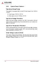
2.2
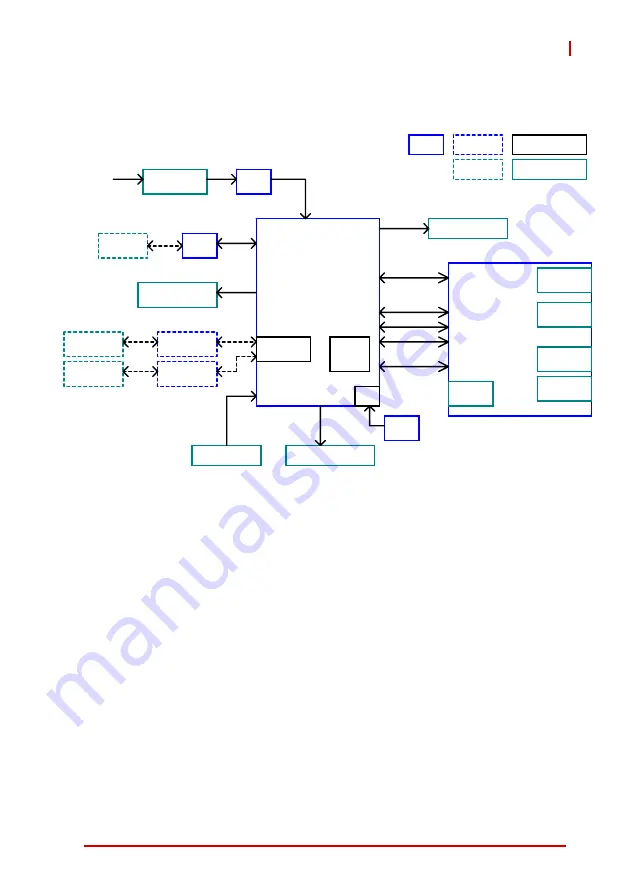
Block Diagram
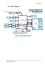
Figure 2-1: DMI-1040 Block Diagram
12 Pin
Power Input
24/36/72/110V (+/-40%)
up to 154VDC
Power
Board
Main Board
Intel Atom x5-E3930
Power
Board
SATA
CFast Slot
SODIMM
DDR3L
Socket
Mini PCIe
Conn x1
Power/Customer
LED x1
RS485 DB9x2
(F+Male)
12V
MVB
Module (opt.)
RS232 DB9x2
(Male)
RS-232
Module (opt.)
Touch Panel
I2C
10.4" LCD Module
Light
Sensor
Speaker x2
(L+R)
12V,5V,
3V3 Bus
PCIe x4
USB 2.0 x2
USB 3.0 x2
LPC
AFM
Board
USB 3.0
Type A x1
Ethernet
M12 Port x3
USB 2.0
M8 Port x1
RS232
Port x1
RS422
Port x1
PCBA
Optional
Optional
Internal I/O
External I/O
5-wire
LVDS &
Back Light
Содержание DMI-1040
Страница 8: ...viii Table of Contents This page intentionally left blank...
Страница 10: ...x List of Figures This page intentionally left blank...
Страница 12: ...xii List of Tables This page intentionally left blank...
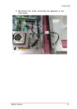
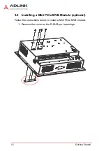
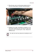
Страница 27: ...Getting Started 15 DMI 1040 6 Disconnect the cable connecting the speakers to the main board...
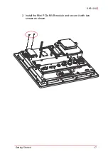
Страница 29: ...Getting Started 17 DMI 1040 2 Install the Mini PCIe MVB module and secure it with two screws as shown...
Страница 40: ...28 Getting Started This page intentionally left blank...
Страница 45: ...Driver Installation 33 DMI 1040 Click Next The system will begin installing the Wi Fi driver...
Страница 66: ...54 Driver Installation This page intentionally left blank...


