Cooling System
45
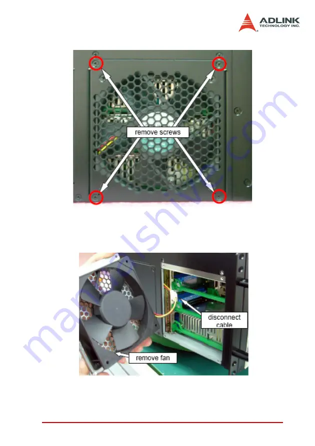
Figure 4-6: Remove the left-side exhaust fan module screws
2. Pull the fan module out of the chassis by the front edge,
disconnect the power cable, and replace with a func-
tional fan module.
Figure 4-7: Remove the left exhaust fan module and
disconnect the power cable
3. Reverse steps 1-2 to replace the fan module.
Содержание cPCIS-6418U Series
Страница 4: ......
Страница 8: ...iv...
Страница 13: ...Introduction 5 Dimensions in mm Figure 1 3 cPCIS 6418U Top View Figure 1 4 cPCIS 6418U Side View...
Страница 23: ...Backplanes 15 3 3 Mechanical Drawing Power Section Figure 3 1 cBP 6814U Backplane Front View...
Страница 26: ...18 Backplanes Figure 3 4 cBP 6814U Backplane Rear View...
Страница 27: ...Backplanes 19 Figure 3 5 cBP 6814U N110 Backplane Rear View...
Страница 32: ...24 Backplanes 5V Connector CN11 3 3V Connector CN12 Pin Signal 1 5V 2 GND Pin Signal 1 3 3V 2 GND...
Страница 46: ...38 Backplanes...
Страница 48: ...40 Cooling System Mechanical Drawing Figure 4 1 System Alarm Board Mechanical Drawing...
Страница 58: ...50 Cooling System...
Страница 62: ...54 Power Supply Unit...


