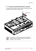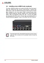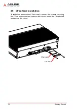
18
Getting Started
Leading
EDGE COMPUTING
3.2
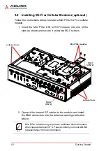
Installing Wi-Fi or Cellular Modules (optional)
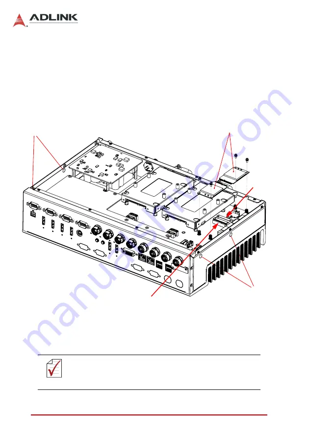
Follow the instructions below to install a Mini PCIe Wi-Fi or cellular
module.
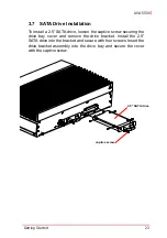
1. Insert the Mini PCIe LTE or Wi-Fi module into one of the
slots as shown and secure it using two M2.5 screws.
2. Connect the internal RF cables to the module and install
the SMA connectors into the antenna openings indicated
above.
NOTE:
NOTE:
Mini PCIe modules may require an additional thermal solution
when operated above 60 °C. Please contact your local ADLINK
representative for more information.
Mini PCIe modules
antenna holes
antenna holes
Slot 1
Slot 2
(CN12)
(CN14)
Содержание AVA-5500 Series
Страница 8: ...viii Table of Contents Leading EDGE COMPUTING This page intentionally left blank ...
Страница 10: ...x List of Figures Leading EDGE COMPUTING This page intentionally left blank ...
Страница 12: ...xii List of Tables Leading EDGE COMPUTING This page intentionally left blank ...
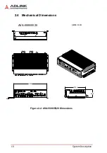
Страница 23: ...System Description 11 AVA 5500 Figure 2 3 AVA 5510 Dimensions 360 225 1 105 4 6 units mm AVA 5510 ...
Страница 76: ...64 BIOS Setup Leading EDGE COMPUTING This page intentionally left blank ...


