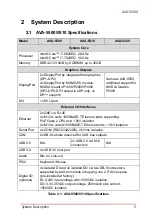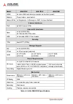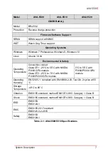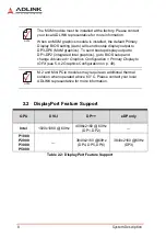
System Description
9
AVA-5500
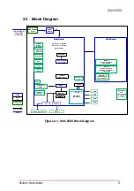
2.3
Block Diagram
Figure 2-1: AVA-5500 Block Diagram
Main Board
Intel® Core™ i7-6820EQ
Intel® Core™ i7-7820EQ
QM170 Chipset
Power
Board
AFM Board
Power conn.
M12 S-coded
4-pin
+24/+36VDC or
+72/+110VDC
(+/- 40%) input
12V
PCBA
Internal
IO
Board-to-Board
Cable
External
IO
DDR4 2133 8GB
up to 32GB
DisplayPort
x2
mPCIe x2
DisplayPort
from MXM x4
DVI-I
GbE (RJ-45)
x2
Ethernet
M12 X-code GbE x4
PoE Class 2 (7W per port)
1.5kV isolation
Ethernet
M12 A-code GbE x4
1.5kV isolation
DB-9 COM x4
with 2kV isolation
(RS232/422/485)
CAN Bus
DB9 x2
PS/2 x1
USB 3.0
Type A x4
mic-in
line-out
PCIe M.2
2280 key type x1
USIM x2
MXM x1
CFast socket
x1
SATA interfaces for
2.5" SSD
PIS-5500 x2
PIS-5510 x4
SSD
SSD
SSD
SSD
Buttons
Power/Reset
M5 threaded
stud
(or equivalent)
for protective
grounding
Antenna plug holes x4
SODIMM x2
SATA x4
DB9 x2
for CAN
(optional)
LTE
Содержание AVA-5500 Series
Страница 8: ...viii Table of Contents Leading EDGE COMPUTING This page intentionally left blank ...
Страница 10: ...x List of Figures Leading EDGE COMPUTING This page intentionally left blank ...
Страница 12: ...xii List of Tables Leading EDGE COMPUTING This page intentionally left blank ...
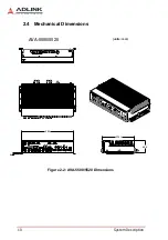
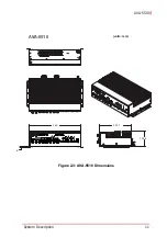
Страница 23: ...System Description 11 AVA 5500 Figure 2 3 AVA 5510 Dimensions 360 225 1 105 4 6 units mm AVA 5510 ...
Страница 76: ...64 BIOS Setup Leading EDGE COMPUTING This page intentionally left blank ...


