


Connecting Input Signals
Adept IO Blox User’s Guide, Rev B
29
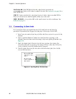
3.4
Connecting Input Signals
The IO Blox has 16 optically isolated digital I/O channels (8 high-side driver outputs with
common source and 8 independent inputs). They are wired to terminal blocks located on
the IO Blox. See
. These terminal blocks also contain internally wired
jumpers to route ground and power signals, if desired.
NOTE:
In V+ systems, the IO Blox inputs cannot be used for REACTI
programming, high-speed interrupts, or vision triggers. See the
for information on digital I/O programming.
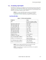
Input Specifications
NOTE:
The input current specifications are provided for reference.
Voltage sources are typically used to drive the inputs.
NOTE:
If using multiple power supplies, ground all the power supplies to
the same grounding point.
Table 3-1. IO Blox Input Specifications
Parameter
Value
Style
Two wire, individually optically
isolated, reversible current flow.
Operational voltage range
0 to 30 VDC
“Off” state voltage range
0 to 3 VDC
“On” state voltage range
10 to 30 VDC
Typical threshold voltage
V
in
= 8 VDC
Operational current range
0 to 7.5 mA
“Off” state current range
0 to 0.5 mA
“On” state current range
2.5 to 7.5 mA
Typical threshold current
2.0 mA
Impedance (V
in
/I
in
)
3.9 K
Ω
minimum
Current at V
in
= +24 VDC
I
in
≤
6 mA
Turn on response time (hardware)
Software scan rate/response time
5 µsec maximum
16 ms scan cycle/
32 ms max. response time
Turn off response time (hardware)
Software scan rate/response time
5 µsec maximum
16 ms scan cycle/
32 ms max. response time
Содержание IO Blox
Страница 26: ...Chapter 2 Installation 26 Adept IO Blox User s Guide Rev B...
Страница 51: ......
Страница 52: ...3011 Triad Drive Livermore CA 94551 925 245 3400 P N 04638 000 Rev B...